Construct a coherent view of your software system with an expertly designed UML diagram. This guide will cover everything you need to know about UML composite structure diagrams, including what they are and how to build one.
What is a composite structure diagram?
A composite structure diagram is a UML structural diagram that provides a logical overview of all or part of a software system. It acts as a look inside a given structured classifier, defining its configuration classes, interfaces, packages, and the relationships between them at a micro-level.
Benefits of composite structure diagrams
A composite structure diagram allows users to see exactly what is contained within an object, specifying how different properties fit together to produce a certain behavior. The different relationships within a complex software system can be difficult to understand, but decomposing a system’s functionality can provide valuable insight into how structures are interconnected, how information is communicated, and more.
A composite structure diagram also provides these benefits:
- Helps users understand the current state of their system
- Breaks down the internal structure of multiple classes, interfaces, or components, and their interactions
- Details runtime architectures and usage patterns not found in static diagrams
- Provides users with information to optimize and troubleshoot their system
Basic components of a composite structure diagram
A composite structure diagram is composed of a number of UML symbols that represent individual parts of a system, as well as relationships between them. Use Lucidchart’s UML shape library to build out your composite structure diagram with the icons below.
| Symbol | Name | Description |
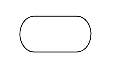 | Terminator | Indicates start and end points |
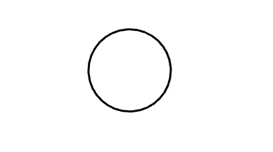 | Node (circular) | Represents events or milestones and contain numbers |
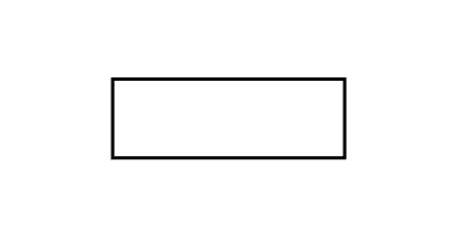 | Node (rectangular) | Represents events or milestones and contain numbers |
 | Actor | Interacts with the system from outside of the system (i.e., person, equipment, etc.) |
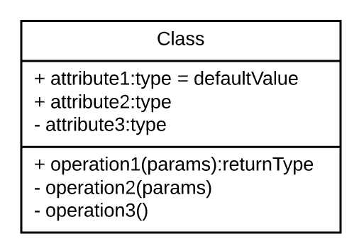 | Class | Groups objects with common properties or behaviors (i.e., common operations, parameters, attributes, etc.) |
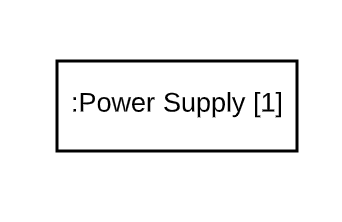 | Part | Acts as a runtime instance of classes or interfaces |
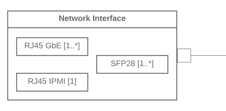 | Port | Acts as an interaction point between a classifier instance (or its behavior) and its environment |
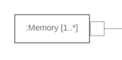 | Interface | Specifies behavior that the implementor agrees to meet |
 | Connector | Illustrates communication between parts |
Composite structure diagram vs class diagram
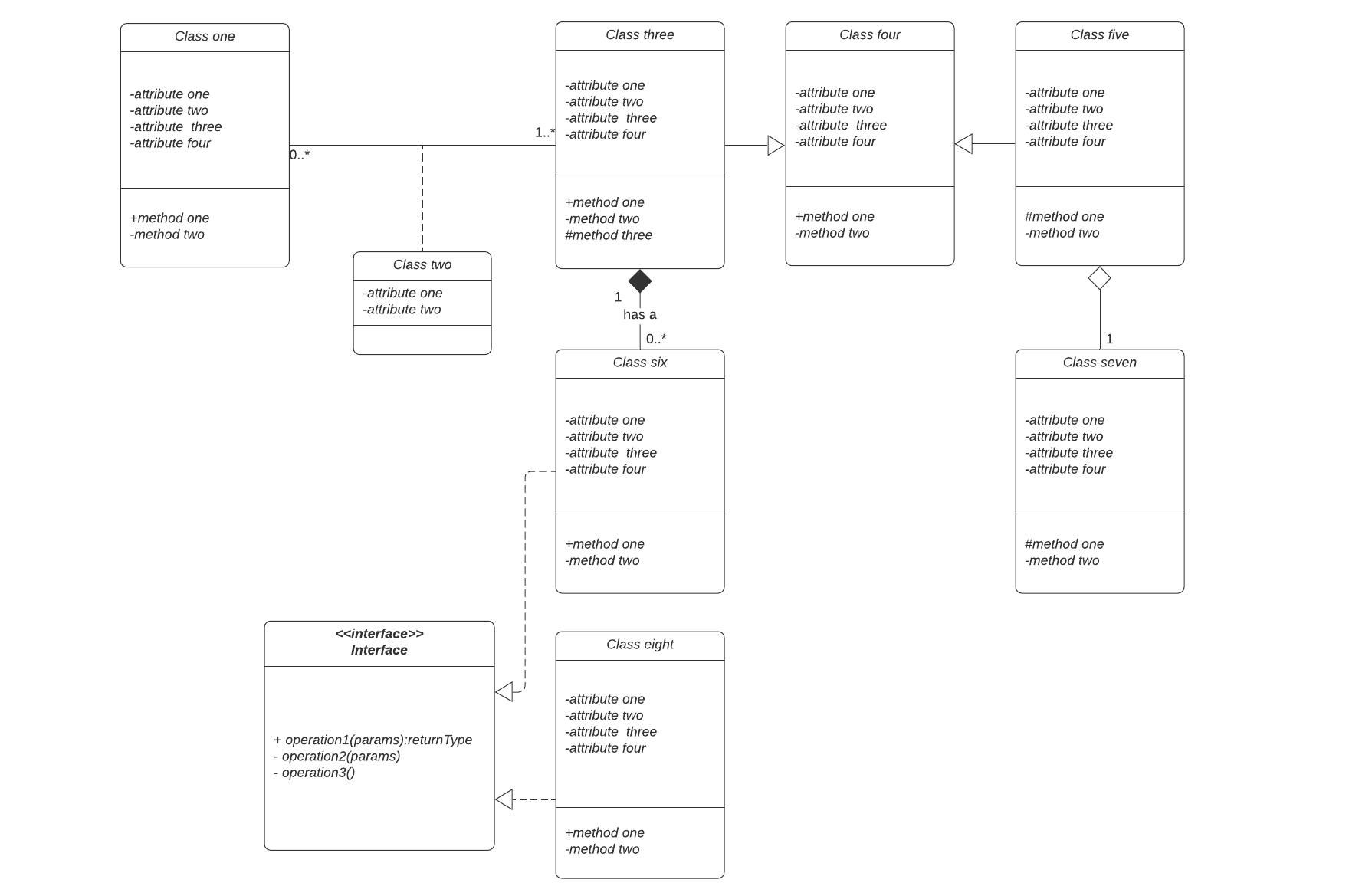
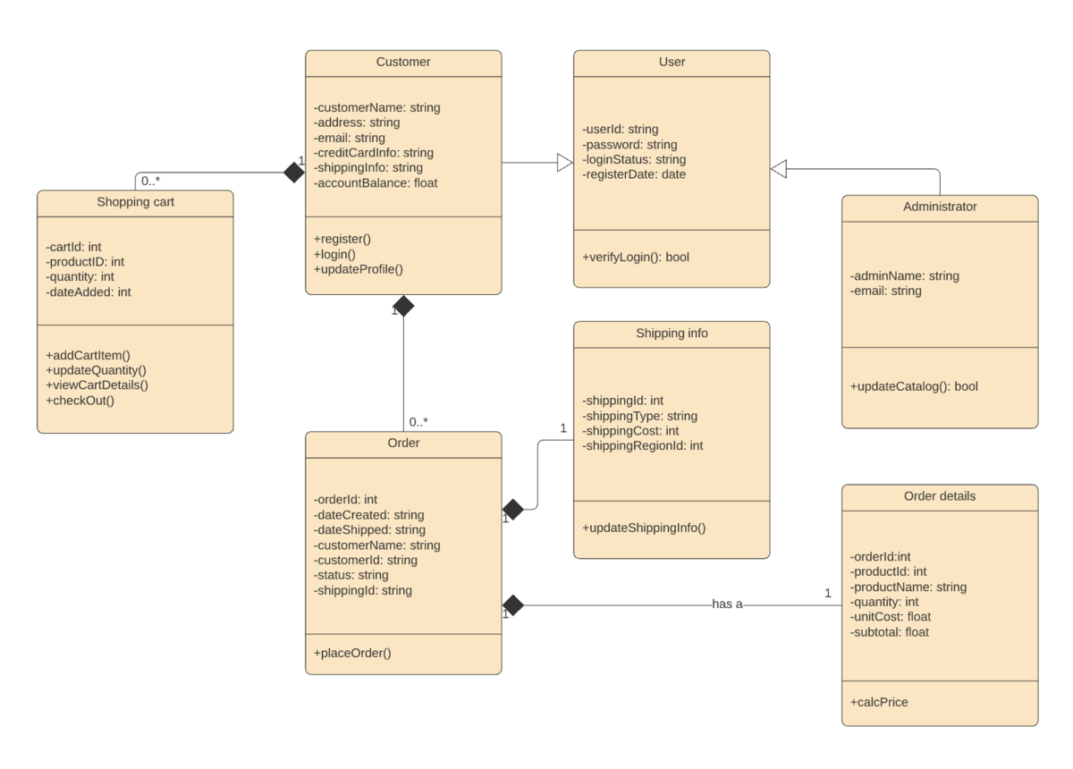
As UML diagrams, both composite structure diagrams and class diagrams are used to visualize and organize the actors, interactions, and artifacts within a system. But while composite structure diagrams and class diagrams have similar meanings, they are ultimately different in how they express those meanings. Simply put, composite structure diagrams are more specific and less ambiguous than class diagrams.
A composite structure diagram allows users to more clearly model the implementations of an artifact’s activity within a runtime. They’re also more adept in depicting decomposition in context, describing the internal structure of multiple classes and the set relationships between them. Simply put, if you’d like to convey concrete, explicit information about the behaviors and relationships within your system, a composite structure diagram is your best choice.
How to make a composite structure diagram
Constructing a composite structure diagram from scratch is easy with Lucidchart. Get started by following the steps below to make a UML composite structure diagram:
- Open a blank document or start with a template from our template gallery.
- Enable the UML shape library by clicking “Shapes” on the left side of the workspace. Then, check “UML” in the workspace manager and click “Save” to enable your changes.
- Create your first component by clicking and dragging your first shape onto the canvas. Continue to add components until each part of your system is represented.
- Group components into classes and interfaces as needed by nesting them within a larger shape or with lollipop and socket shapes. Label the shape accordingly.
- Add ports to each component, class, or interface to depict interaction points. Label each port.
- Add nodes to represent additional types and instances within your system.
- Model your system’s process flow by drawing lines between the appropriate ports and components.
Composite structure diagram example
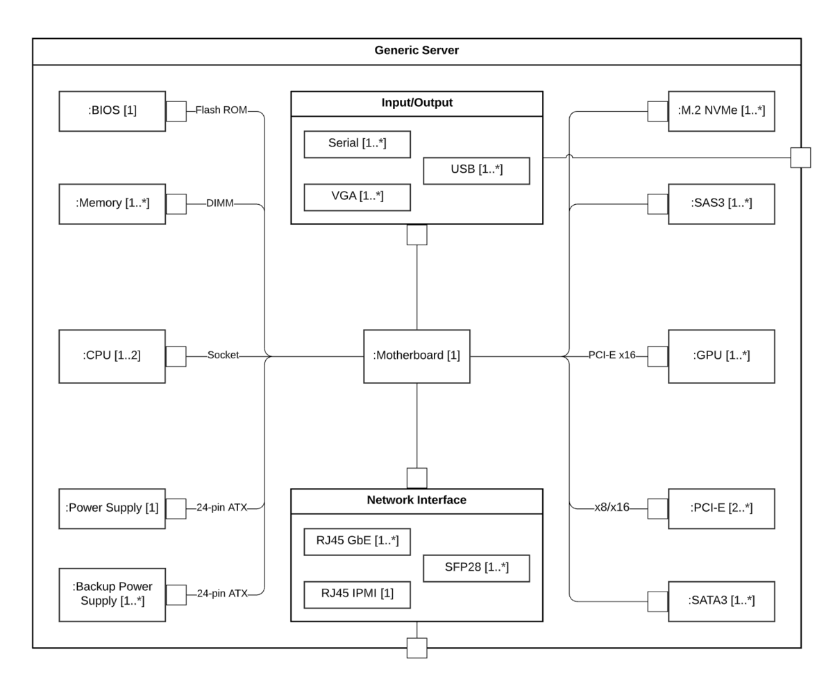
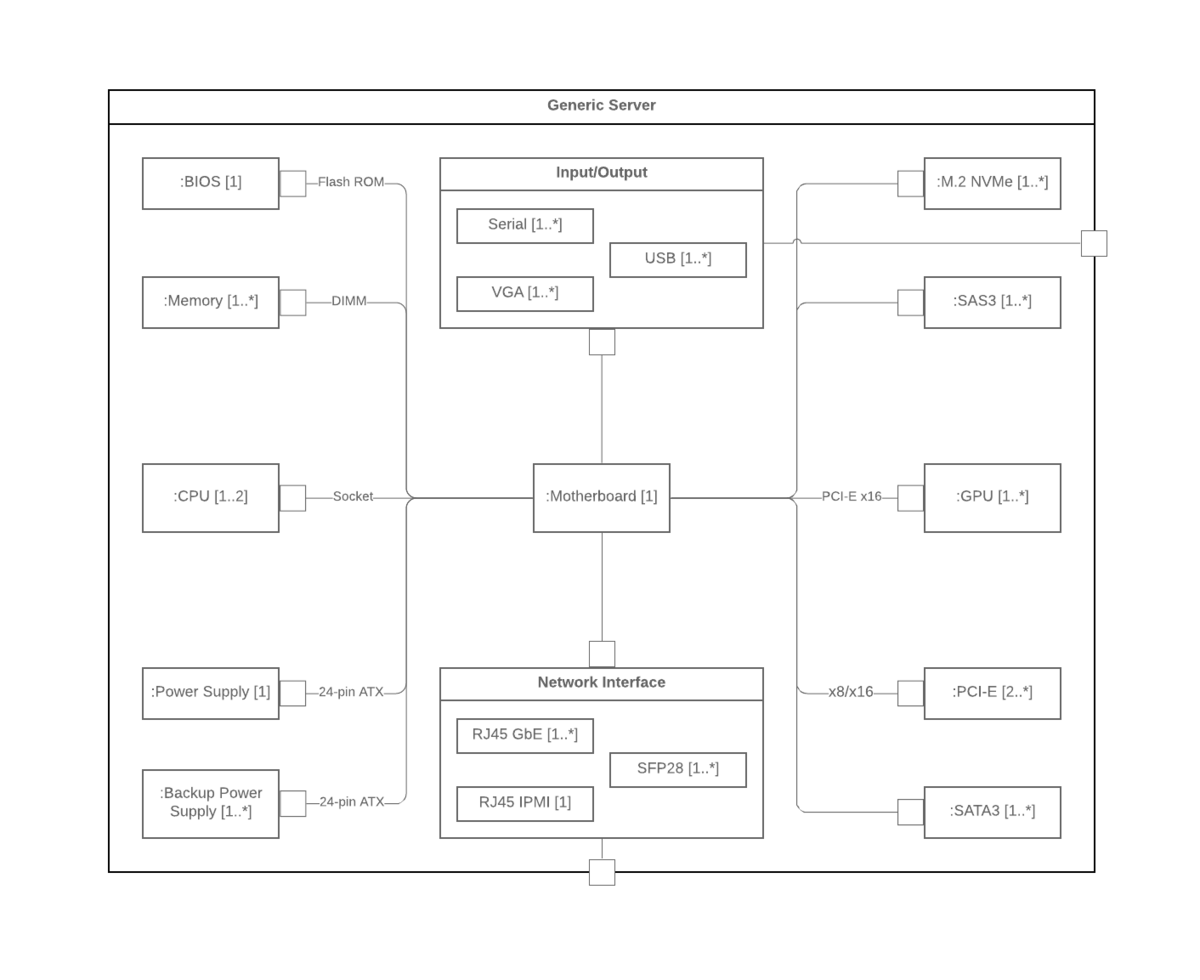
The following template models the internal structure of a generic server classifier. Click the example below to modify the template as needed to visualize the internal structure, interactions, and behaviors of collaborations within your classifier.
Everything you need to make a diagram
Make a polished, professional diagram for free with Lucidchart. No matter what you have in mind, we have the tools you need to build it. Make an account and start diagramming today.
Sign up free