A picture is worth a thousand words. That's why Unified Modeling Language (UML) was created to provide a common visual language in the complex world of software development that would also be understandable for business users and anyone who wants to understand a system. This guide covers everything you need to know about UML. Even if you first encountered UML in formal training and haven’t used it much since, it remains a practical way to keep complex systems understandable—especially when used as living documentation rather than a one-time deliverable.
What is UML?
The Unified Modeling Language (UML) was created to forge a common, semantically and syntactically rich visual modeling language for the architecture, design, and implementation of complex software systems both structurally and behaviorally.
It is analogous to the blueprints used in other fields and consists of different types of diagrams. In aggregate, UML diagrams describe the boundary, structure, and the behavior of the system and the objects within it. When you're writing code, there are thousands of lines in an application, and it's difficult to keep track of the relationships and hierarchies within a software system. UML diagrams divide that software system into components and subcomponents.
There are four problem-solving model categories: imperative, functional, declarative, and object-oriented languages. In object-oriented languages, algorithms are expressed by defining “objects” and having the objects interact with each other. Those objects are things to be manipulated, and they exist in the real world. They can be buildings, widgets on a desktop, or human beings.
Object-oriented languages dominate the programming world because they model real-world objects. UML is a combination of several object-oriented notations: object-oriented design, object modeling technique, and object-oriented software engineering.
UML uses the strengths of these three approaches to present a more consistent methodology that's easier to use. UML represents best practices for building and documenting different aspects of software and business system modeling. Because UML is standardized, it can be applied across programming languages and development processes, making it broadly readable by most software developers.
In practice, UML is also a form of visual documentation that can reduce time spent re-explaining a system. This documentation can help engineers in a number of ways, from onboarding new employees to giving stakeholders a quick overview of the system so developers don't waste time in meetings.
The history and origins of UML
Grady Booch, James Rumbaugh, and Ivar Jacobson, also known as “The Three Amigos” of software engineering, teamed up to provide clarity for programmers by creating new standards.
The efforts of this group resulted in the release of the UML 0.9 and 0.91 documents in 1996. It soon became clear that several organizations, including Microsoft, Oracle, and IBM saw UML as critical to their own business development. They, along with many other individuals and companies, established resources that could develop a full-fledged modeling language. The Three Amigos published The Unified Modeling Language User Guide in 1999 and an update in 2005, which includes UML 2.0.
The role of the Object Management Group (OMG) in UML
According to their website, the Object Management Group® (OMG®) is an international, open membership, not-for-profit technology standards consortium, founded in 1989. OMG standards are driven by vendors, end users, academic institutions and government agencies. OMG Task Forces develop enterprise integration standards for a wide range of technologies and an even wider range of industries. OMG's modeling standards, including the UML and Model Driven Architecture® (MDA®), enable powerful visual design, execution, and maintenance of software and other processes.
OMG oversees the definition and maintenance of UML specifications. This oversight gives engineers and programmers the ability to use one language for many purposes during all phases of the software lifecycle for all system sizes.
The OMG defines the purpose of the UML as:
-
Providing system architects, software engineers, and software developers with tools for analysis, design, and implementation of software-based systems as well as for modeling business and similar processes.
-
Advancing the state of the industry by enabling object visual modeling tool interoperability. However, to enable meaningful exchange of model information between tools, agreement on semantics and notation is required.
UML meets the following requirements:
-
Setting a formal definition of a common Meta-Object Facility (MOF)-based meta-model that specifies the abstract syntax of the UML. The abstract syntax defines the set of UML modeling concepts, their attributes, and their relationships, as well as the rules for combining these concepts to construct partial or complete UML models.
-
Providing a detailed explanation of the semantics of each UML modeling concept. The semantics define, in a technology-independent manner, how the UML concepts are to be realized by computers.
-
Specifying the human-readable notation elements for representing the individual UML modeling concepts, as well as rules for combining them into a variety of different diagram types corresponding to different aspects of modeled systems.
-
Defining ways in which UML tools can be made compliant with this specification. This is supported (in a separate specification) with an XML-based specification of corresponding model interchange formats (XMI) that must be realized by compliant tools.
Types of UML diagrams
UML uses elements and associates them in different ways to form static diagrams (which represent structural aspects of a system) and behavioral diagrams (which represent dynamic aspects of a system). To the uninitiated, it may seem as though there are an infinite number of UML diagrams, but in actuality, UML standards identify 14 types of diagrams that are divided into two groups, defined below.
Structural UML diagrams
-
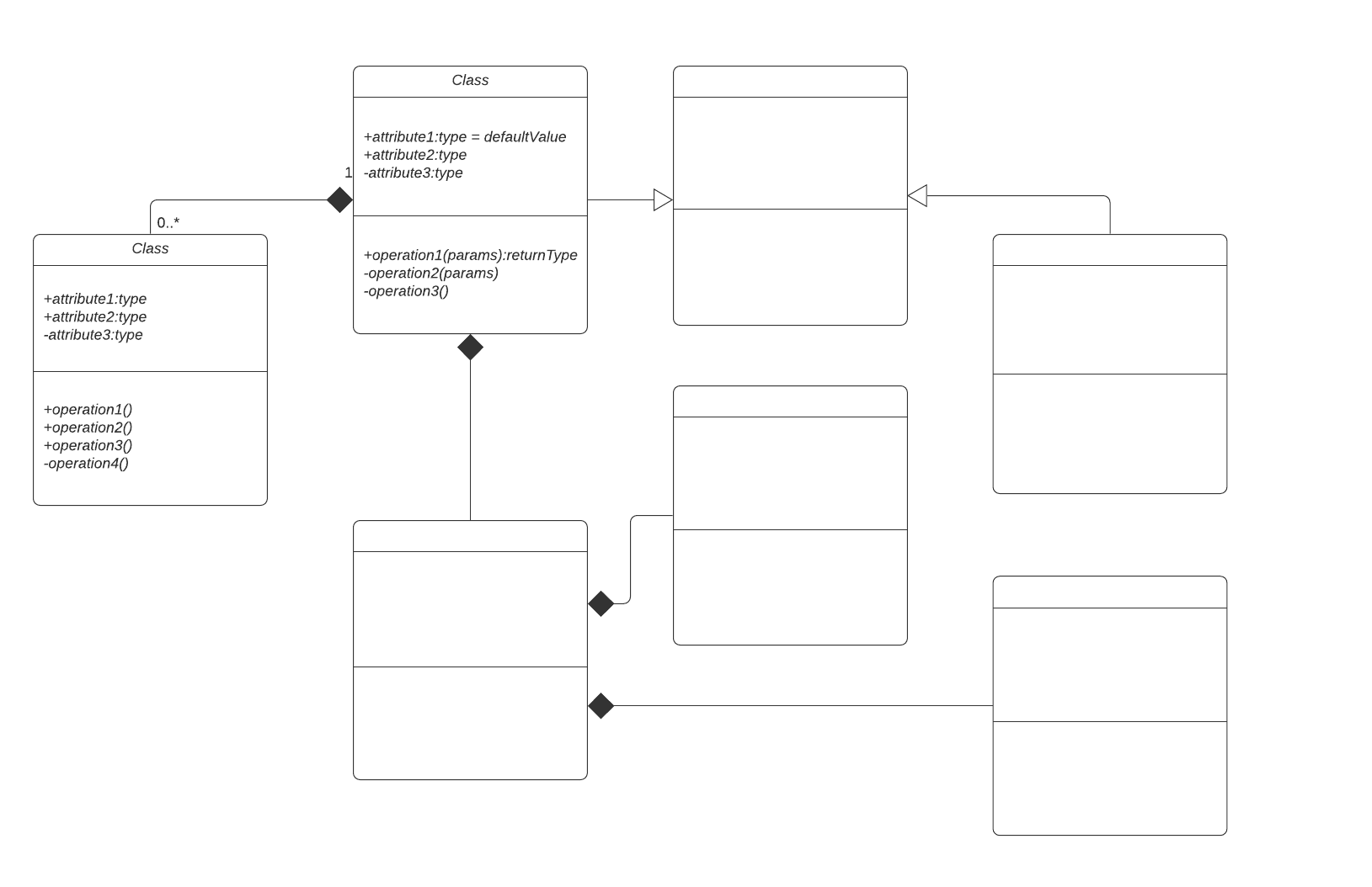
Class diagram: This is the most commonly used UML diagram and the principal foundation of any object-oriented solution. It shows classes within a system, attributes and operations, and the relationship between each class. Classes are grouped together to create class diagrams when diagramming large systems. A class is represented by a rectangle that contains three compartments stacked vertically: The top compartment contains the class's name and is mandatory, but the bottom two compartments give details about the class attributes and class operations or behaviors.
-
Component diagram: A component diagram is essentially a more specialized version of the class diagram—the same notation rules apply for both. A component diagram breaks a complex system down into smaller components and visualizes the relationship between those components.
-
Composite structure diagram: These types of diagrams are essentially the blueprints for the internal structure of a classifier. They can also be used to show the behavior of a collaboration or the classifier's interactions with its environment through ports. They can easily depict the internal components of any hardware to more thoroughly understand the inner workings.
-
Deployment diagram: These diagrams are most useful to systems engineers and typically show performance, scalability, maintainability, and portability. When hardware components are displayed in relation to each other, it's easier to keep track of your entire hardware mesh and make sure that all elements are accounted for in a deployment.
-
Object diagram: Object diagrams show examples of data structures at a specific time. You could use a class diagram to show a structure and then use object diagrams as test cases to verify the completeness of your class diagram. Or you could create an object diagram to discover information about model elements and their links.
-
Package diagram: Package diagrams are used to show dependencies between different packages in a system. A package, depicted as a file folder, organizes model elements, such as use cases or classes, into groups. There are two special types of dependencies defined between packages: package import and package merge.
-
Profile diagrams: Profile diagrams are also part of the UML standard and are primarily used when you need to tailor UML for a particular domain. Recently added to UML 2.0, profile diagrams are unique and rarely used in any specification. A profile diagram is best understood as an extensibility mechanism for customizing UML models for specific domains and platforms.
Behavioral UML diagrams
-
Activity diagrams: Activity diagrams are used as an alternative to state machine diagrams. Activity diagrams visualize the steps performed in a use case—the activities can be sequential, branched, or concurrent. This type of UML diagram is used to show the dynamic behavior of a system, but it can also be useful in business process modeling.
-
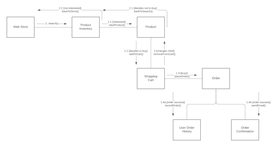
Communication diagram: Communication diagrams, which used to be called collaboration diagrams, show how objects relate to each other. They model the way objects associate and connect through messages within an architectural design of a system. They can also show alternative scenarios within use cases or operations that require the collaboration of different objects and interactions.
-
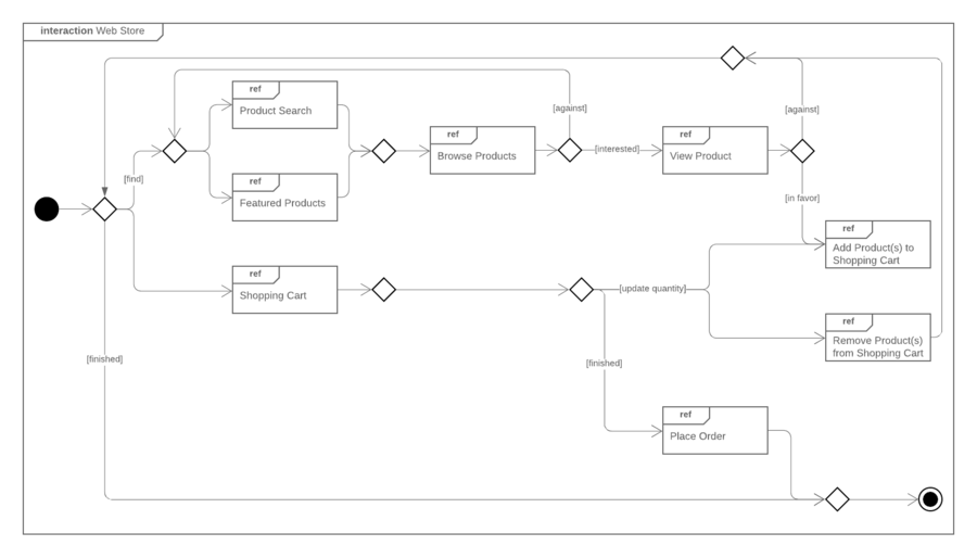
Interaction overview diagram: This diagram overviews the flow of control between interacting nodes. They include initial nodes, flow final nodes, activity final nodes, decision nodes, merge nodes, fork nodes, and join nodes.
-
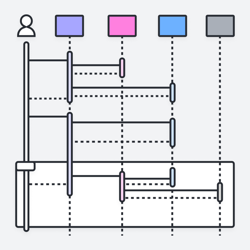
Sequence diagram: A sequence diagram, sometimes referred to as an event diagram or an event scenario, shows the order in which objects interact. This way, you can visually represent simple runtime scenarios.
-
State diagram: State diagrams, simply put, depict states and transitions. A state refers to the different combinations of information that an object can hold, and this UML diagram can visualize all possible states and the way the object transitions from one state to the next.
-
Timing diagram: Often described as an inverted sequence diagram, a timing diagram shows how objects interact with each other in a given timeframe. Use these diagrams to see how long each step of a process takes and find areas for improvement.
-
Use case diagram: Use case diagrams model how users, displayed as stick figures called "actors," interact with the system. This type of UML diagram should be a high-level overview of the relationships between actors and systems, so it can be a great tool for explaining your system to a non-technical audience.
UML terms glossary
Familiarize yourself with the UML vocabulary, with this list culled from the UML 2.4.1 document, intended to help OMG non-members understand commonly used terms.
-
Abstract syntax compliance: Users can move models across different tools, even if they use different notations.
-
Common Warehouse Metamodel (CWM): Standard interfaces that are used to enable interchange of warehouse and business intelligence metadata between warehouse tools, warehouse platforms and warehouse metadata repositories in distributed heterogeneous environments
-
Concrete syntax compliance: Users can continue to use a notation they are familiar with across different tools.
-
Core: In the context of UML, the core usually refers to the "core package," which is a complete metamodel particularly designed for high reusability.
-
Language unit: Consists of a collection of tightly coupled modeling concepts that provide users with the power to represent aspects of the system under study according to a particular paradigm or formalism
-
Level 0 (L0): Bottom compliance level for UML infrastructure, a single language unit that provides for modeling the kinds of class-based structures encountered in most popular object-oriented programming languages
-
Meta Object Facility (MOF): An OMG modeling specification that provides the basis for metamodel definitions in OMG's family of MDA languages
-
Metamodel: Defines the language and processes from which to form a model
-
Metamodel Constructs (LM): Second compliance level in the UML infrastructure, an extra language unit for more advanced class-based structures used for building metamodels (using CMOF) such as UML itself. UML only has two compliance levels.
-
Model Driven Architecture (MDA): An approach and a plan to achieve a cohesive set of model-driven technology specifications
-
Object Constraint Language (OCL): A declarative language for describing rules that apply to Unified Modeling Language. OCL supplements UML by providing terms and flowchart symbols that are more precise than natural language but less difficult to master than mathematics.
-
Object Management Group (OMG): A not-for-profit computer industry specifications consortium whose members define and maintain the UML specification
-
UML 1: First version of the Unified Modeling Language
-
Unified Modeling Language (UML): A visual language for specifying, constructing, and documenting the artifacts of systems
-
XMI: An XML-based specification of corresponding model interchange formats
Modeling concepts specified by UML
System development focuses on three overall different system models:
- Functional: These are use case diagrams, which describe system functionality from the point of view of the user.
- Object: These are class diagrams, which describe the structure of the system in terms of objects, attributes, associations, and operations.
- Dynamic: Interaction diagrams, state machine Diagrams, and activity diagrams are used to describe the internal behavior of the system.
These system models are visualized through two different types of diagrams: structural and behavioral.
Object-oriented concepts in UML
The objects in UML are real-world entities that exist around us. In software development, objects can be used to describe, or model, the system being created in terms that are relevant to the domain. Objects also allow the decomposition of complex systems into understandable components that allow one piece to be built at a time.
Here are some fundamental concepts of an object-oriented world:
- Objects: Represent an entity and the basic building block
- Class: Blueprint of an object.
- Abstraction: Behavior of a real-world entity
- Encapsulation: Mechanism of binding the data together and hiding them from the outside world
- Inheritance: Mechanism of making new classes from an existing one
- Polymorphism: Defines the mechanism to exists in different forms
In modern teams—especially those practicing Agile—these object-oriented concepts are often easiest to communicate when diagrams are treated as “core documentation” and updated alongside the code, rather than created once and left to go stale.
Why teams still use UML diagrams (especially in Agile)
If you've had any sort of formal code training, you were probably introduced to UML diagrams in school. But how much have you used them after that point? Because UML diagrams take some time to build and become out of date fairly quickly in an Agile environment, many software developers have forgotten about them.
That concern is valid: Diagrams that don’t evolve with a project quickly lose value. But when kept current, UML can make development faster and communication clearer. Though many engineers dread diagrams, they're useful in an Agile development environment. They keep development productive and focused. Instead of thinking of them as just a "nice to have," treat your UML diagrams as core aspects of documentation.
UML diagrams can help engineering teams:
-
Bring new team members or developers switching teams up to speed quickly.
-
Navigate source code.
-
Plan out new features before any programming takes place.
-
Communicate with technical and non-technical audiences more easily.
However, diagrams that don't evolve with a project are useless, so it's necessary to have constantly evolving diagrams. One way teams reduce the maintenance burden is by generating diagrams from more lightweight inputs (for example, text-based definitions) so documentation stays elastic as the system changes. Lucidchart can generate UML sequence diagrams from text markup, which makes diagramming automatic and elastic.
How to make a UML diagram
UML diagrams follow a specific set of rules and shapes, and you could spend a significant amount of time learning how to correctly build each type. Luckily, we've made it easy for you with easy tutorials, starting with class diagrams, that walk you through the process step by step.
Regardless of tooling, the practical workflow is consistent: Pick the diagram type that matches your question (structure vs. behavior), model only what you need for the current audience, and revisit the diagram as the code and requirements change. Whether you are mapping out the static architecture of a new software system or visualizing dynamic user interactions, follow these steps to build an effective model:
1. Define your goal
Determine exactly what you need to visualize. Ask yourself if you need to map the static structure of a system (structural) or show how components interact and change over time (behavioral).
2. Choose the right diagram type
Based on your system requirements, select the appropriate UML diagram. For example, use a class diagram for object-oriented system structure, a sequence diagram for time-ordered interactions, or a use case diagram to illustrate user functionality. (Tip: Starting with one of Lucidchart’s premade UML templates is the fastest way to begin.)
3. Enable UML shape libraries
Because UML uses a strict visual vocabulary, you need the correct symbols. In Lucidchart, click "More shapes" at the bottom of the left-hand menu, search for "UML," and check the boxes for the specific shape libraries you need (e.g., UML class, UML state, UML sequence).
4. Add and define your shapes
Drag and drop entities, objects, nodes, or actors onto your canvas. Arrange them logically, and double-click inside the shapes to add custom text, specific attributes, and operations to your objects.
5. Connect your components
Establish relationships between your entities by drawing lines between them. Customize the line endpoints (arrowheads, diamonds, etc.) to accurately reflect specific UML relationships, such as inheritance, composition, dependencies, or basic associations.
6. Review and collaborate
UML is designed to serve as a shared language between developers, engineers, and business stakeholders. Once your diagram is drafted, use Lucidchart's real-time collaboration features to invite your team to review the architecture, leave comments, and finalize the blueprint.
Become a UML evangelist
Sometimes it's not enough for you to be on board the UML diagramming train. After all, as a software developer, you're usually working with teams, and it's important to get everyone else along for the ride.
If your team is reluctant to integrate UML diagrams into the development process, propose using them for just one project to start. Once your team sees what a boon UML diagrams are to documentation, they'll be more willing to start making them a necessary step.
Plus, with Lucidchart, UML diagrams aren’t a chore: They're an asset.
Everything you need to make a diagram
Make a polished, professional diagram for free with Lucidchart. No matter what you have in mind, we have the tools you need to build it. Make an account and start diagramming today.
Sign up free