Communication diagrams, formerly known as collaboration diagrams, are almost identical to sequence diagrams in UML, but they focus more on the relationships of objects—how they associate and connect through messages in a sequence rather than interactions. With our UML diagramming tool, refer to this guide on everything you need to know when planning and creating a communication diagram in UML.
What is a communication diagram?
A communication diagram offers the same information as a sequence diagram, opens in a new tab, but while a sequence diagram emphasizes the time and order of events, a communication diagram emphasizes the messages exchanged between objects in an application. Sequence diagrams can fall short of offering the "big picture.”
This is where communication diagrams come in and offer that broader perspective within a process. You can draw your own communication diagram using our free UML software, opens in a new tab.
A communication diagram offers the same information as a sequence diagram, opens in a new tab, but while a sequence diagram emphasizes the time and order of events, a communication diagram emphasizes the messages exchanged between objects in an application. Sequence diagrams can fall short of offering the "big picture.”
This is where communication diagrams come in and offer that broader perspective within a process. You can draw your own communication diagram using our free UML software, opens in a new tab.
Basic components of a communication diagram
Communication diagrams offer benefits similar to sequence diagrams, but they will offer a better understanding of how components communicate and interact with each other rather than solely emphasizing the sequence of events. They can be a useful reference for businesses, organizations, and engineers who need to visualize and understand the physical communications within a program. Try drawing a sequence diagram to:
- Model the logic of a sophisticated procedure, function, or operation.
- Identify how commands are sent and received between objects or components of a process.
- Visualize the consequences of specific interactions between various components in a process.
- Plan and understand the detailed functionality of an existing or future scenario.
Symbols and notations of communication diagrams
The symbols and notations used in communication diagrams are the same notations for sequence diagrams, opens in a new tab.
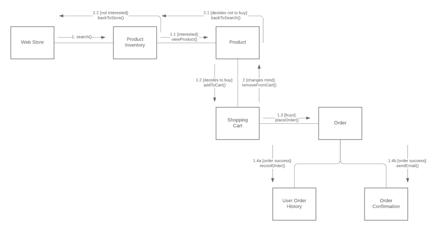
- Rectangles represent objects that make up the application.
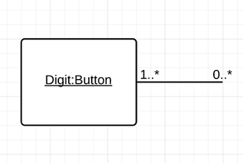
- Lines between class instances represent the relationships between different parts of the application.
- Arrows represent the messages that are sent between objects.
- Numbering lets you know in what order the messages are sent and how many messages are required to finish a process.
Communication diagram example
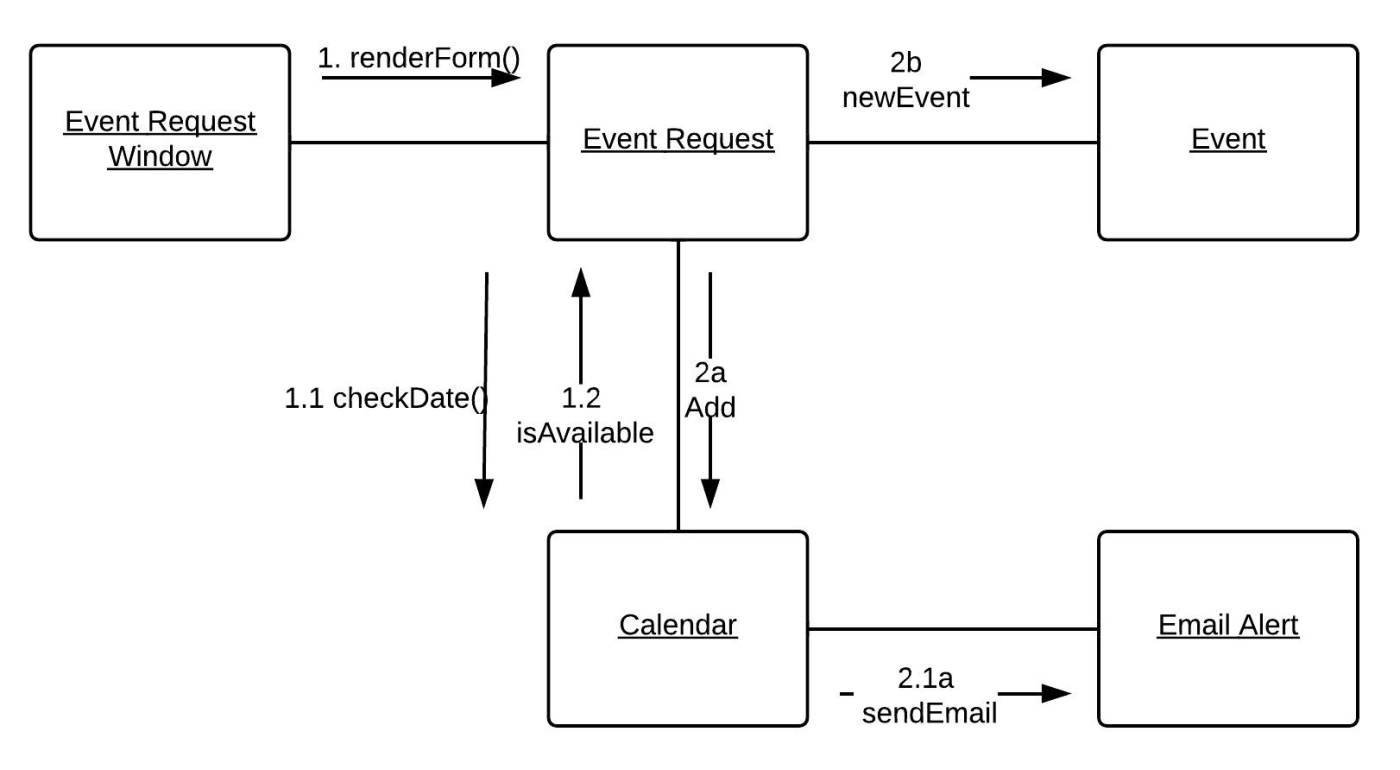
In the example below, the communication diagram explains the process to add an event to a calendar. Even in simple examples like this one, you’ll notice the exact commands and requests being shared between various steps in the process. The numbers on each line represent the order and options in which they are activated. We know that some actions happen concurrently because of the use of letters.
How to draw a communication diagram in UML
UML encompasses a wide range of diagrams and notation styles, so it may be helpful to revisit the basics. This page can help you understand what a communication diagram is, opens in a new tab, and this Unified Modeling Language tutorial, opens in a new tab explains essential concepts of UML. The symbols found in communication diagrams are the same symbols used in sequence diagrams, opens in a new tab.
In order to successfully create a communication diagram in UML, it’s imperative that you understand the difference between communication and sequence diagrams. Sequence diagrams chart the timing and order in which messages are sent and received within a sequence. In contrast, communication diagrams focus on the interactions and relationships between objects—hence the name. Both diagrams can be retrofitted to fit the other's structure because the information displayed is so similar.
1. Get started with Lucidchart
If you haven’t registered with Lucidchart, you can sign up for free. Log in and select a template or open a new document. You also have the option to import existing diagrams from Visio, opens in a new tab and build off the work you already started.
2. Add or import UML shapes
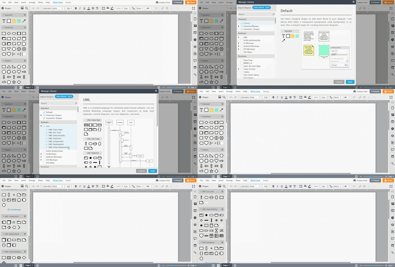
Once you’ve opened a new document in Lucidchart, click “Shapes” on the left side of the editor and turn on the UML shape library, specifically the sequence diagram shapes since communication diagrams use the exact same notations. Adding shapes to the canvas is as easy as dragging and dropping.
Many—though not all—communication diagrams include the swimlane shape. Swimlanes merely separate the system into more manageable chunks, such as distinct areas for each participant. Swimlane shapes can be found in the containers shape library. If you select a swimlane, double-click the header text to replace it with your own title. Use the toolbar above the canvas to add extra rows or columns.
If you don't want to use swimlanes, it's acceptable to arrange elements in a free-form way. You will probably drag out object shapes, actor shapes that represent participants in the system, and lines (known as links) that represent relationships.
3. Add texts and concepts to your communication diagram
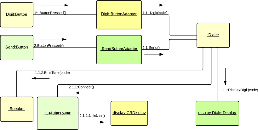
Next to the lines, you can draw arrows to indicate messages. Messages should be labeled with a name and sequence number. The sequence number shows the reader how to move from object to object and message to message, i.e. where the diagram begins and ends.
How to format communication diagrams
Once all of your elements are represented and linked together, take a final look over the document and perform some final formatting. You can select groups of shapes and arrange them to better order and align them evenly. You can also select a pre-made theme from the right sidebar to color your shapes.
4. Publish, implement, and share
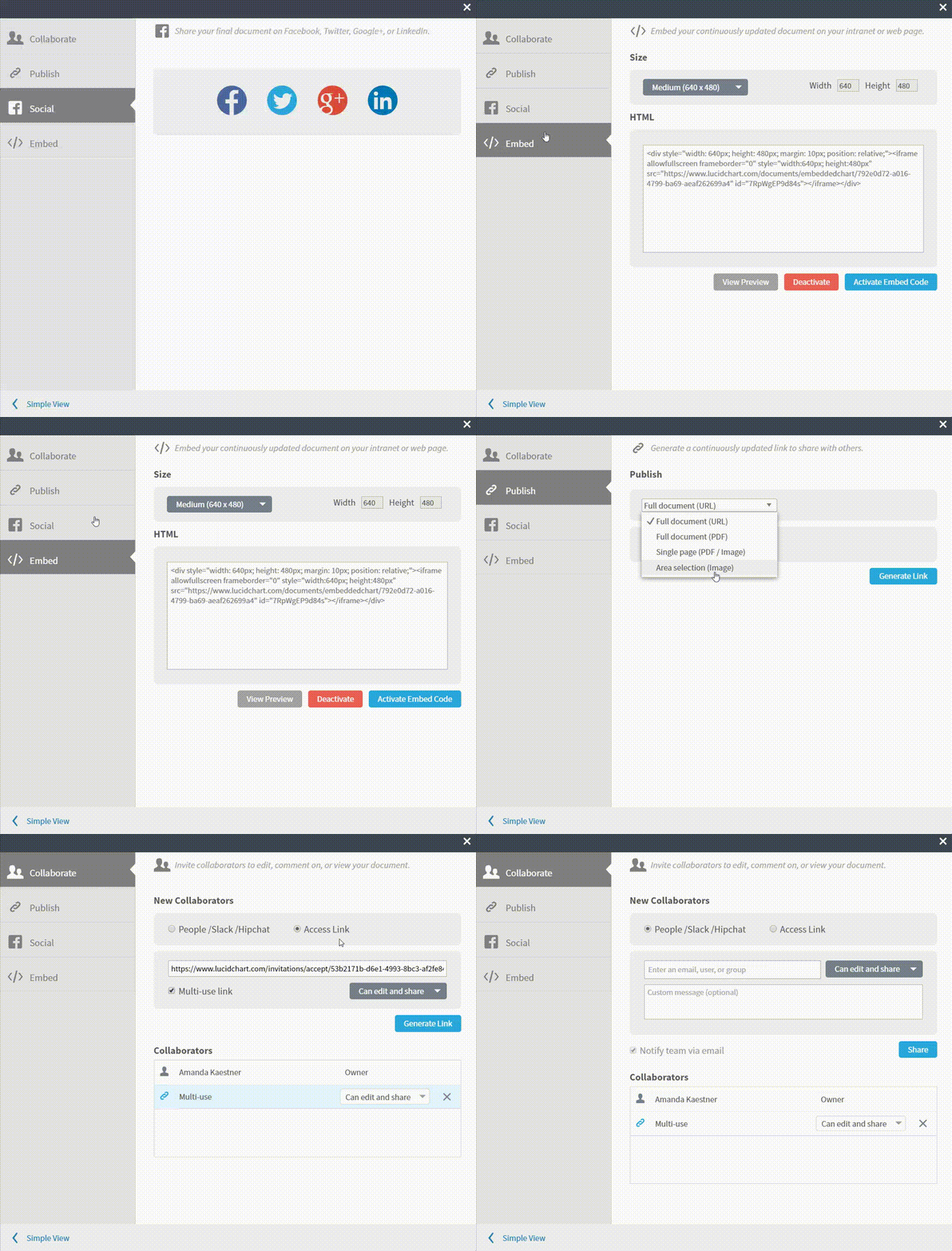
Once you’ve created a professional communication diagram in Lucidchart, you can then share and publish it in a variety of ways. Download your communication diagram in any file format, share it on your favorite social media platforms, or publish it on one of the many apps Lucidchart integrates with, including Google Workspace, Microsoft Office, Confluence, and Jira. Click to see all Lucidchart integrations, opens in a new tab and add diagrams almost anywhere.
Everything you need to make a diagram
Make a polished, professional diagram for free with Lucidchart. No matter what you have in mind, we have the tools you need to build it. Make an account and start diagramming today.
Sign up free