Key takeaways
ER diagram symbols allow you to model a database from a high-level overview to implementation-ready tables.
Entities come in three types—strong, weak, and associative—to represent independent objects, dependent objects, and many-to-many links.
Attributes can be multivalued, derived, or composite, capturing repeating values, calculated values, and grouped sub-attributes within a single entity.
Lucidchart offers dedicated ER shape libraries and exports diagrams to MySQL, PostgreSQL, SQL Server, or Oracle, allowing you to generate a database.
Databases run the modern world. Virtually all businesses use databases to store, organize, and retrieve the information their teams depend on every day. Learning entity-relationship diagram symbols gives engineers and analysts a shared visual language for mapping how that data connects.
An entity-relationship diagram (ERD) shows the entities in a system and the relationships between them, helping technical and non-technical teams visualize the database structure. ERDs focus on data structure rather than the process flows that are captured by data flow diagrams.
Consider this a crash course and refresher on ER diagram notation and symbols. The sections below walk through each symbol, notation style, and data model you need to design clear, accurate ERDs.
Data models
Every ERD fits one of three data models. Each model adds detail as you move from concept toward implementation. The conceptual model is the highest-level view, the logical model adds structure, and the physical model is the most detailed.
Conceptual data model
A conceptual data model captures the important entities in a system and the relationships between them. It does not specify attributes or primary keys. Teams use it as the foundation for building more detailed logical models.
Logical data model
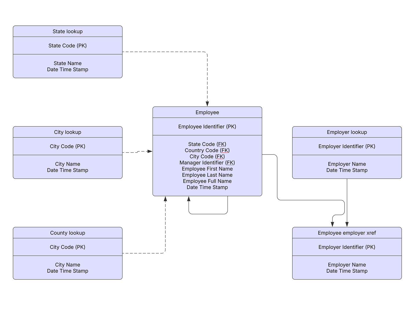
A logical data model includes all entities and relationships, and it specifies attributes, primary keys, and foreign keys for each entity. This stage involves normalization. Normalization removes redundancy by dividing an entity table into two or more tables and defining relationships between them.
Physical data model
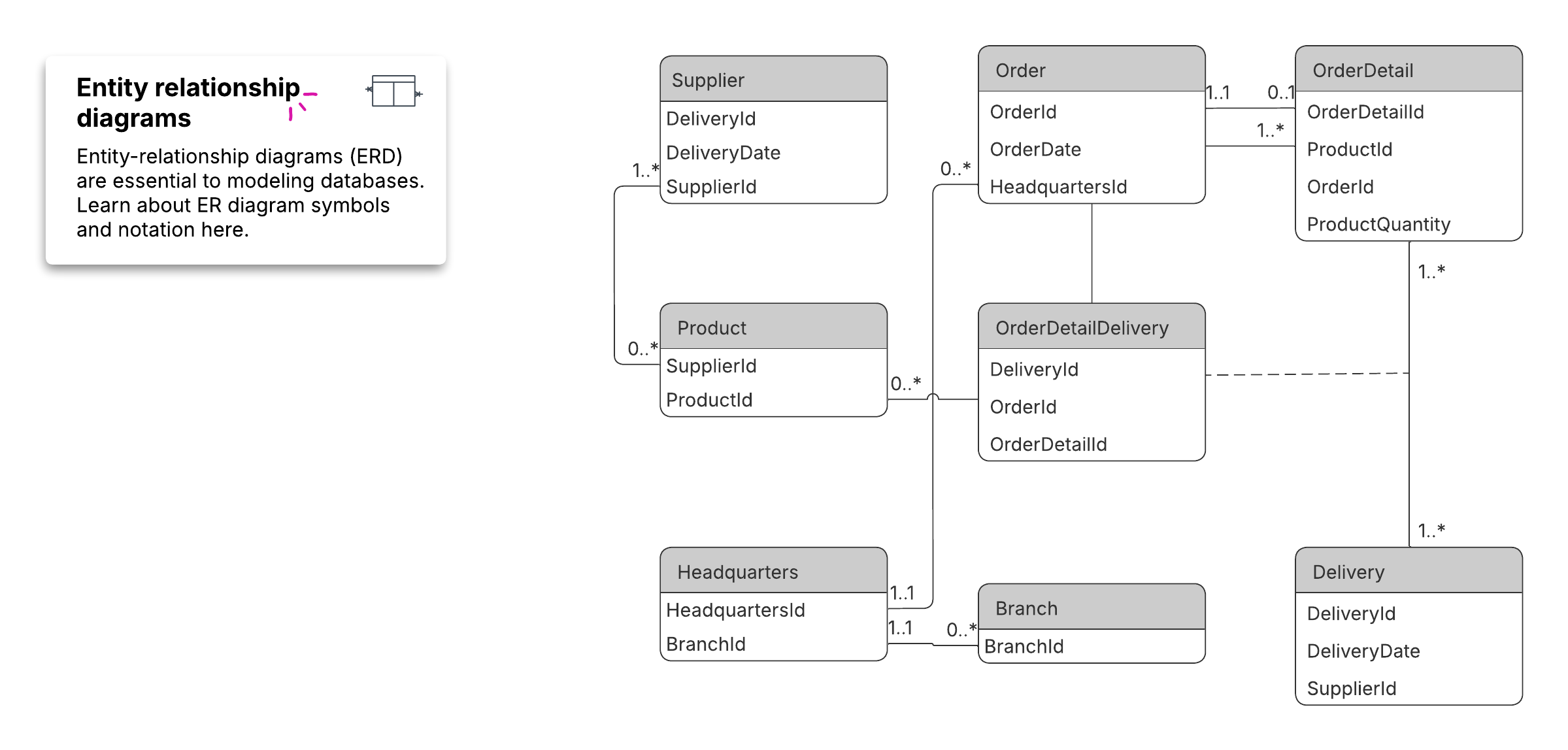
A physical data model shows all tables and columns, including foreign keys that link related tables. It may include denormalization to improve performance, and its structure differs by database management system (DBMS). Because the physical model differs by DBMS, a database design tool helps you generate the right structure for MySQL, Oracle, PostgreSQL, or SQL Server.
Entity-relationship diagram (ERD) tutorial video
This Lucid tutorial walks through building an ERD from scratch, covering entities, attributes, and cardinalities to visualize your database.
Conceptual ERD symbols
You'll find these symbols in the UML Entity Relationship and Entity Relationship shape libraries in Lucidchart's ER diagram tool. Lucid also supports PNG, JPG, and SVG import, so you can bring in existing assets.
Entities
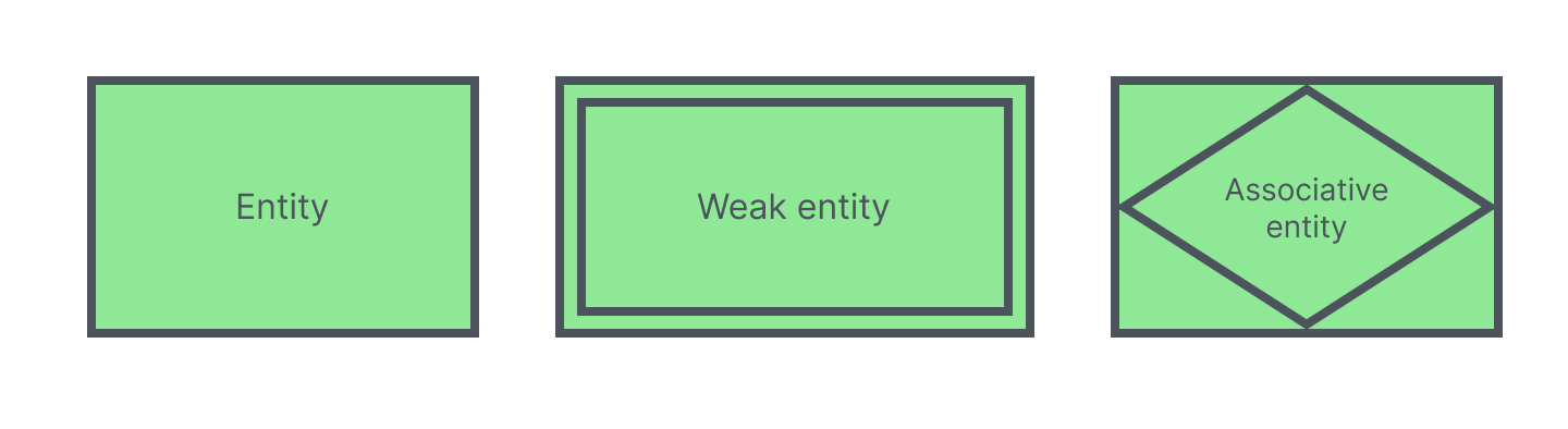
An entity is an object or concept, typically named with a noun. ERDs use three kinds of entities:
Strong entities exist independently and have unique, identifying attributes.
Weak entities depend on an owner entity and have no unique or primary key of their own.
Associative entities associate instances of one or more entity types, which is how an associative entity ERD represents a many-to-many relationship.
Entities also carry keys. A super key, candidate key, and primary key each describe a different level of uniqueness used to identify an entity instance. To model advanced structures like subclasses and specialization, use enhanced entity-relationship diagrams (EERDs).
Relationships
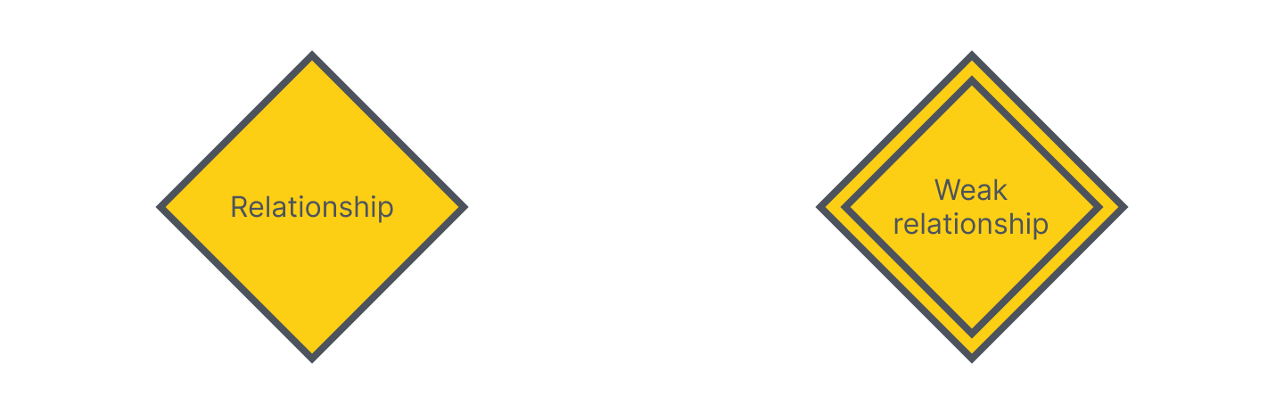
A relationship is a meaningful association between entities, usually named with a verb. Relationships describe how entities interact within the system.
A weak or identifying relationship connects a weak entity to its owner entity. These ERD relationship symbols signal that one entity cannot be identified without the other.
Attributes
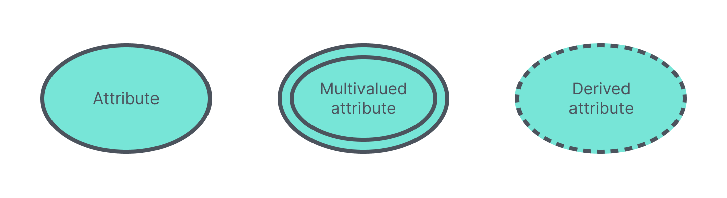
An attribute is a characteristic of an entity or a relationship. ERDs support several attribute types:
Multivalued attributes hold more than one value for a single entity instance.
Derived attributes are calculated from other attributes rather than stored directly.
Composite attributes break down into smaller sub-attributes, which is how a composite attribute in an ER diagram groups related details.
Physical ERD symbols
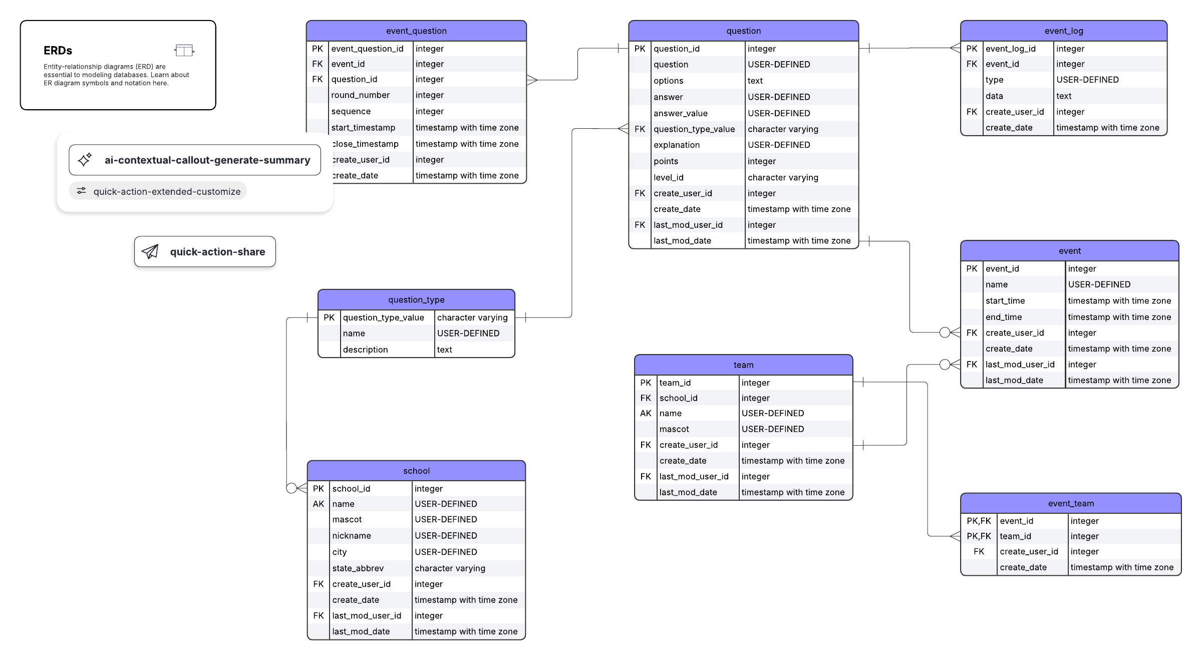
Physical ERD symbols describe how a database is actually implemented. Tables represent entities, fields represent attributes, and each field has a defined type. Keys tie the tables together.
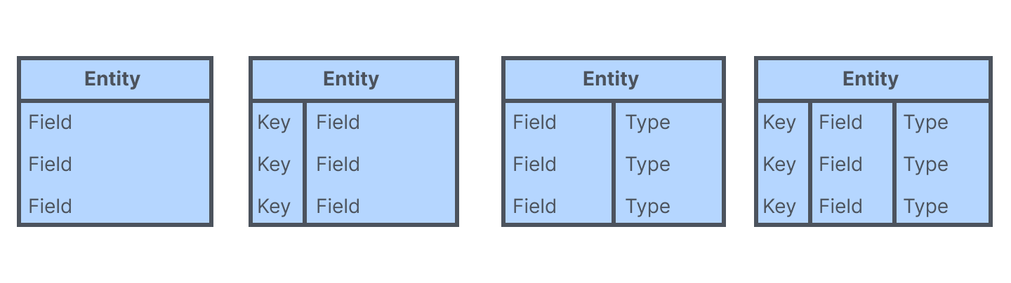
A primary key uniquely identifies one instance of an entity. A foreign key is a primary key referenced in a related entity, linking the two through a one-to-one or one-to-many relationship. A foreign key in an ER diagram enforces referential integrity between tables.
ERD tutorial video: Primary keys, foreign keys, and bridge tables
This Lucid tutorial covers advanced ERD concepts, such as primary keys, foreign keys, and bridge tables, to maintain data integrity and organize complex relationships.
ERD notation and cardinality
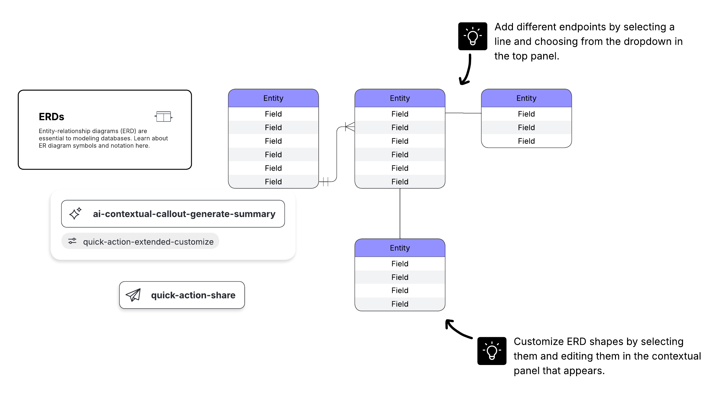
In the physical model of an ERD, relationships appear as stylized lines that connect tables. The symbols on those lines describe cardinality and ordinality. Cardinality is the maximum number of times an instance of one entity can relate to instances of the related entity. Ordinality is the minimum number.

ERDs express three cardinality types:
One-to-one: for example, one customer relates to one mailing address
One-to-many: one customer relates to many orders
Many-to-many: many students relate to many courses
Crow's foot notation is the preferred style in Lucid because it clearly shows both minimum and maximum cardinality on each line. Other notation styles include Chen, Barker, Information Engineering (Martin), OMT, IDEF1X, Bachman, and UML. Learn about these notation styles in our ERD tutorial.
How do you read an ER diagram?
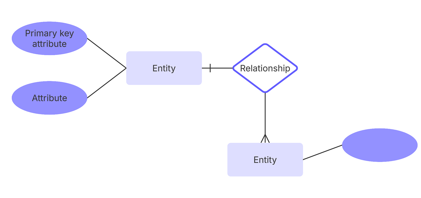
Here are the steps for reading an ER diagram:
Identify the entities or tables in the diagram.
Read each entity's attributes and keys, noting primary and foreign keys.
Follow the connecting lines between related entities to interpret how the entities relate.
Interpret the crow's foot symbols to determine cardinality.
Make an ER diagram in Lucidchart
Lucidchart offers every standard entity-relationship shape, so you can build conceptual and physical ERDs in one place. When your diagram is ready, export it to MySQL, PostgreSQL, SQL Server, or Oracle to generate a database directly from your design.