Key takeaways
P&ID symbols represent the functional relationship between the piping, instrumentation, and equipment that make up a process-industry facility.
The symbols fall into seven main groups: equipment, piping, vessels, heat exchangers, pumps, instruments, and valves.
Instrument symbols follow ISA S5.1, while overall P&ID symbols align with standards such as ISO 10628, ISO 14617, and Europe's EN 62424. Instrument tag bubbles follow the ISA S5.1 lettering scheme to identify each device's function.
No single universal standard exists. Symbols can vary by company, software, and creator, making a shared, standardized legend essential.
A P&ID is more detailed than a process flow diagram (PFD), which usually comes first as the higher-level view.
In Lucidchart, you can access every featured P&ID symbol and import SVG or other image files to build a custom P&ID library.
P&ID symbols are the standardized shapes engineers use to document how a process facility is piped, instrumented, and equipped. This guide breaks the notation into its seven main categories, explains the standards behind it, and shows how to place each symbol on a diagram. Use it as a working reference whether you are designing a new system, reviewing an existing plant, or building a shared legend for your team.
About P&ID symbols
A piping and instrumentation diagram (P&ID) documents the equipment, piping, and control systems of a process-industry facility. The symbols on it represent the functional relationship between piping, instrumentation, and system equipment.
P&ID symbols are organized into seven main groups:
Equipment
Piping
Vessels
Heat exchangers
Pumps
Instruments
Valves
Together, these groups describe what each component does and how fluids and signals move through the system.
There is no single universal standard for P&ID notation. Instrument symbols are generally based on ISA S5.1. Overall, P&ID symbols align with international standards such as ISO 10628 and ISO 14617, and EN 62424 is used in Europe.
Because symbols can still vary by company, software, and individual creator, a shared and standardized legend matters. A clear legend keeps every reader—engineers, operators, and reviewers—interpreting the same shape the same way.
A P&ID is more detailed than a process flow diagram (PFD), opens in a new tab, which is usually the higher-level first step. Teams often start with a PFD to map the overall process, then develop the P&ID to specify instrumentation and control detail.
With our P&ID software, opens in a new tab, it's easy to access all of the featured P&ID symbols. You can also import SVG and other image files to build a custom P&ID library that matches your own conventions.
Equipment symbols
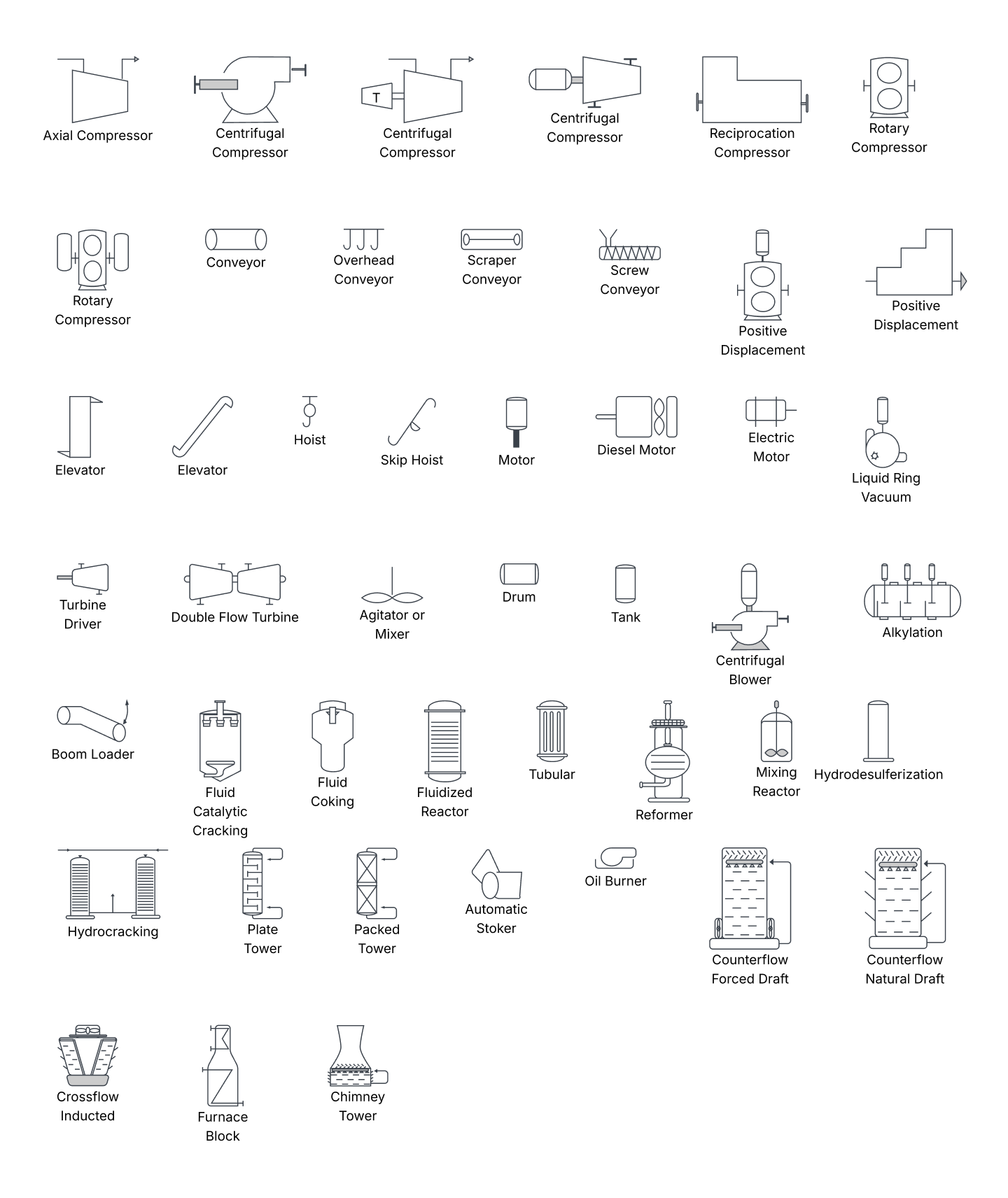
Equipment symbols cover the miscellaneous units that don't fit the other categories. They represent mechanical devices that support a process rather than directly store or route fluid, such as:
Compressors
Conveyors
Motors
Turbines
Vacuums
Piping symbols
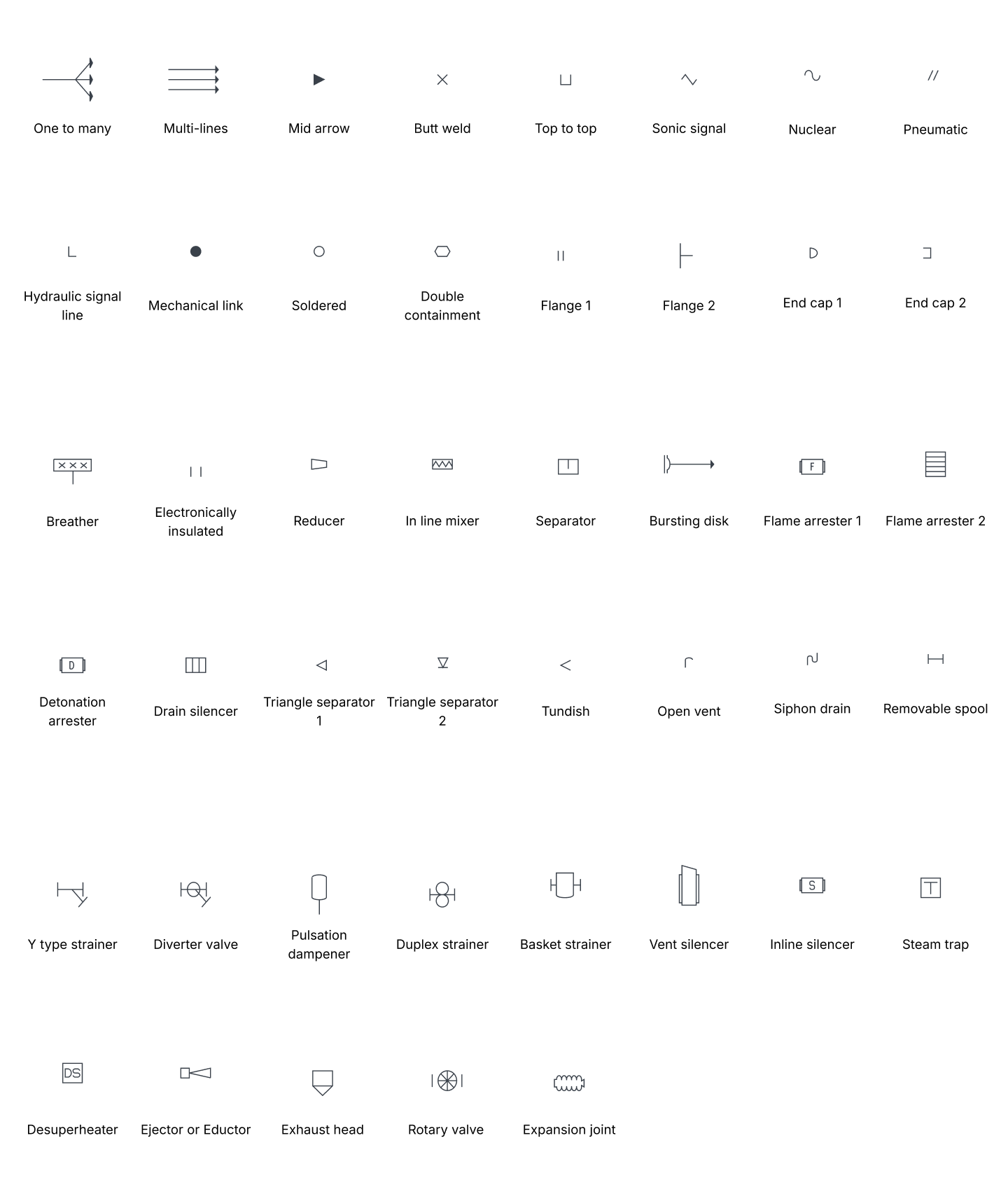
Piping symbols represent the pipes and tubes that transport fluids through the system. They show how routes connect equipment and where flows split or merge. Piping symbols include:
One-to-many pipes
Multi-line pipes
Separators
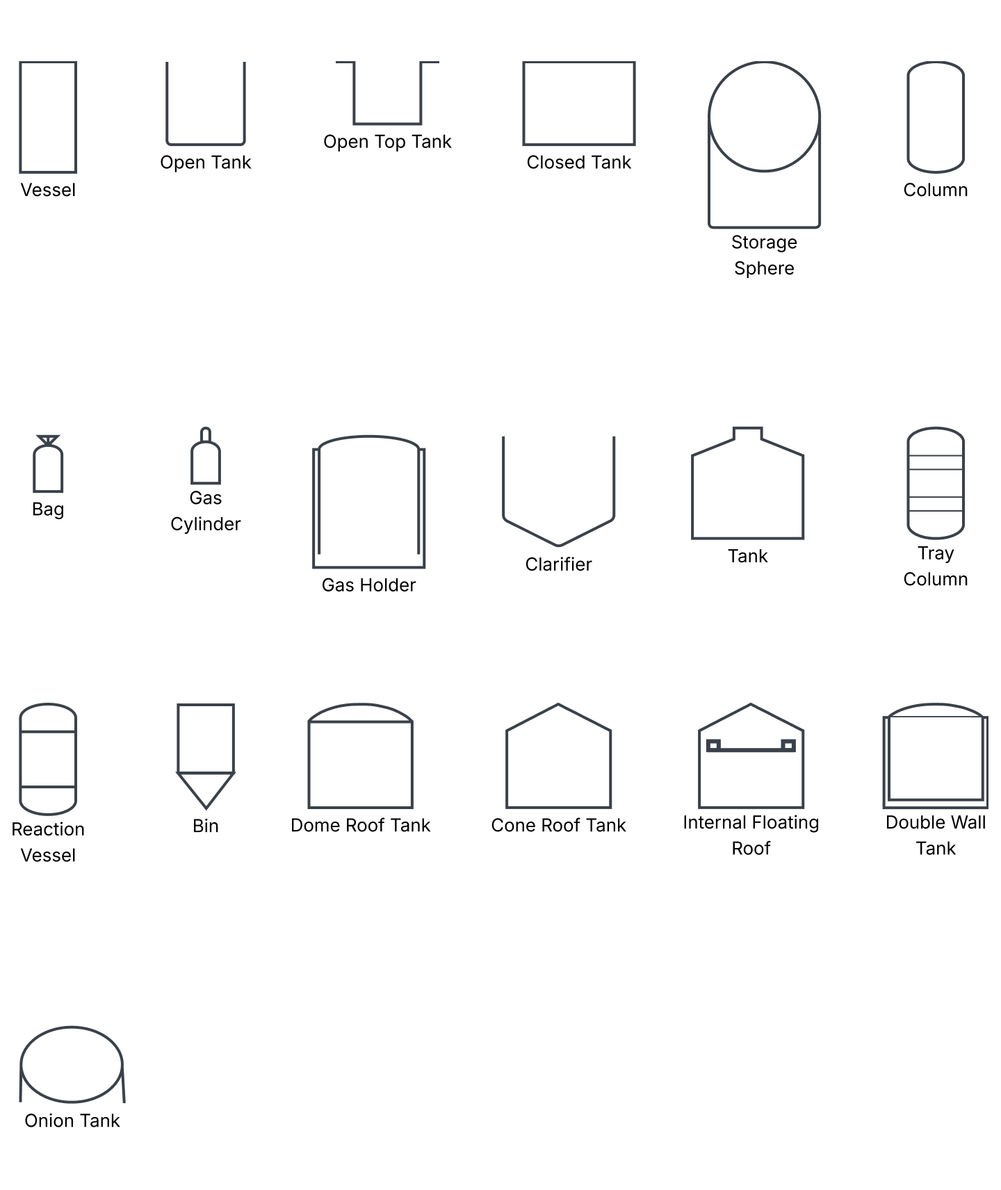
Vessel symbols represent the containers that store fluid within a facility. They vary by shape and function depending on what the vessel holds. Some vessel symbols are:
Tanks
Cylinders
Columns
Bags
Heat exchanger symbols
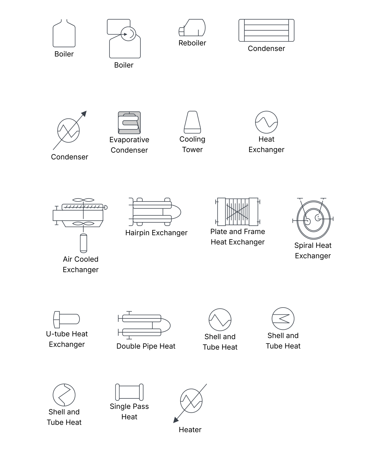
Heat exchanger symbols represent the devices that transfer heat between fluids or systems. They identify where thermal energy is added or removed. These symbols include:
Boilers
Condensers
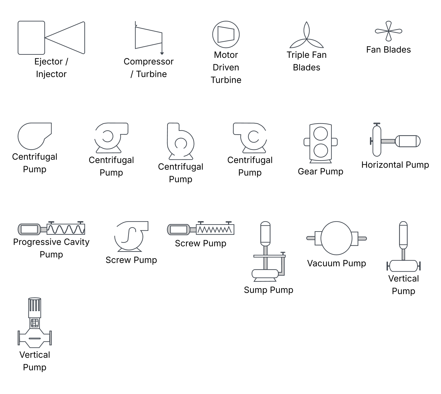
Pump symbols
Pump symbols represent the devices that use suction or pressure to move fluids through the system. This group also includes fans that move air or gas. Examples of pump symbols include:
Pumps, such as a centrifugal pump
Fans
Instrument symbols
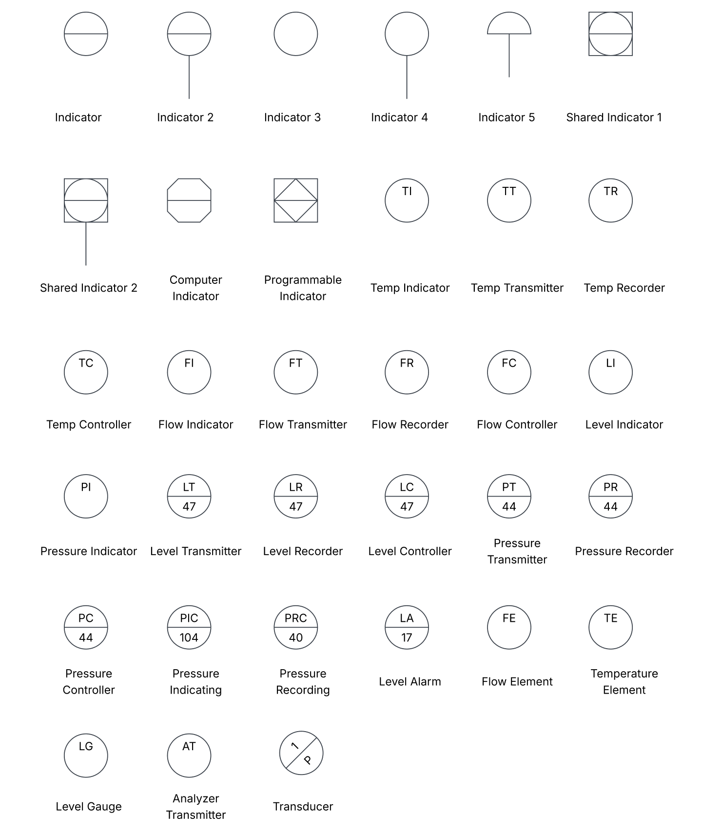
Instrument symbols represent the devices that measure and sometimes control flow, temperature, angle, and pressure. Each instrument tag bubble follows the ISA S5.1 lettering scheme to identify the device's function and loop. Instrument symbols include:
Indicators
Transmitters
Recorders
Controllers
Elements
Valve symbols
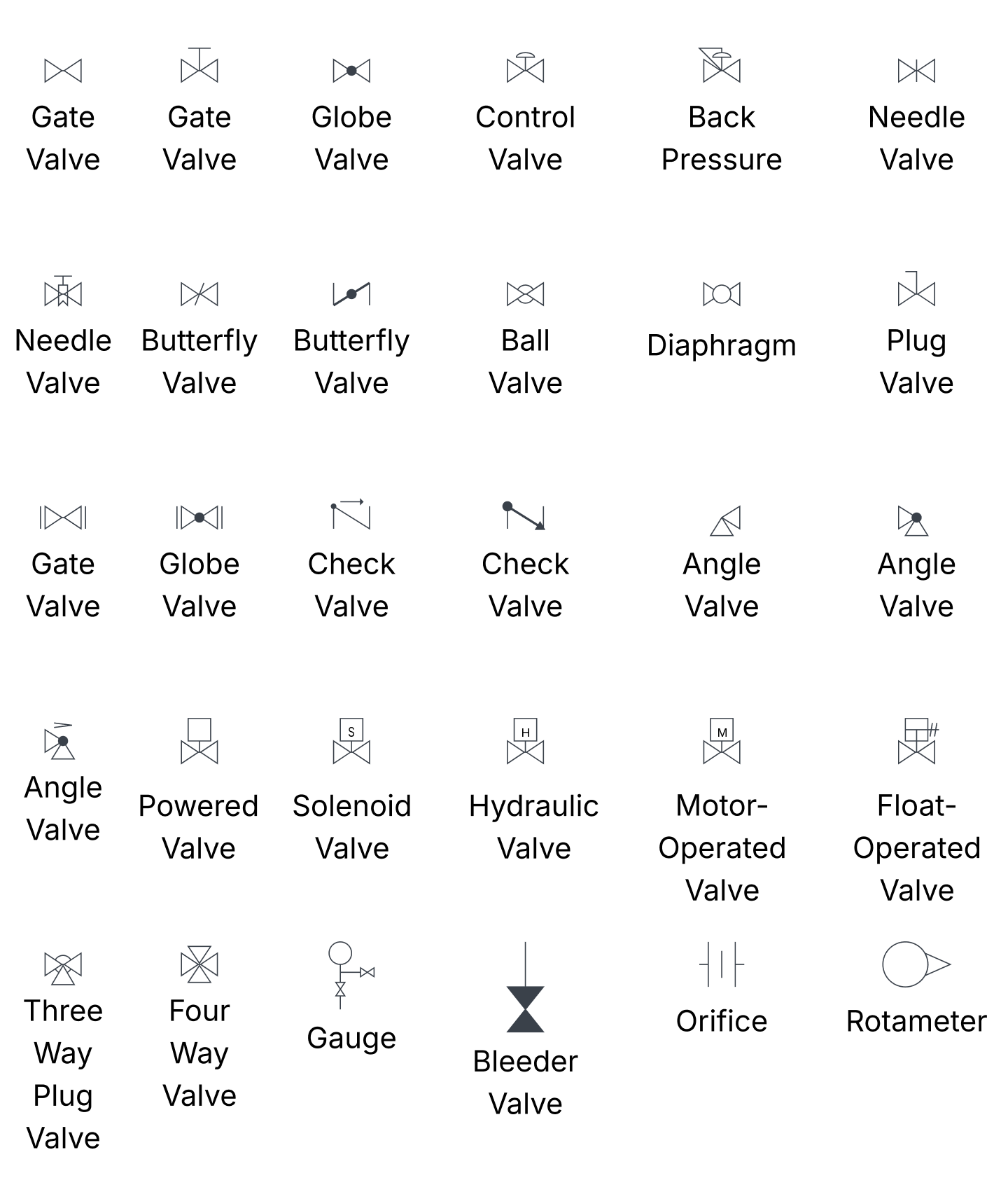
Valve symbols represent the devices that regulate, direct, or control fluid flow. This group includes standard valves along with related flow components. Some valve symbols you may see are:
Rotameters
Orifices
Other valve types
How do you add P&ID symbols in Lucidchart?
You add P&ID symbols by enabling the process engineering shape library, then dragging the shapes you need onto the canvas. From there, you connect, label, and import custom shapes if needed.
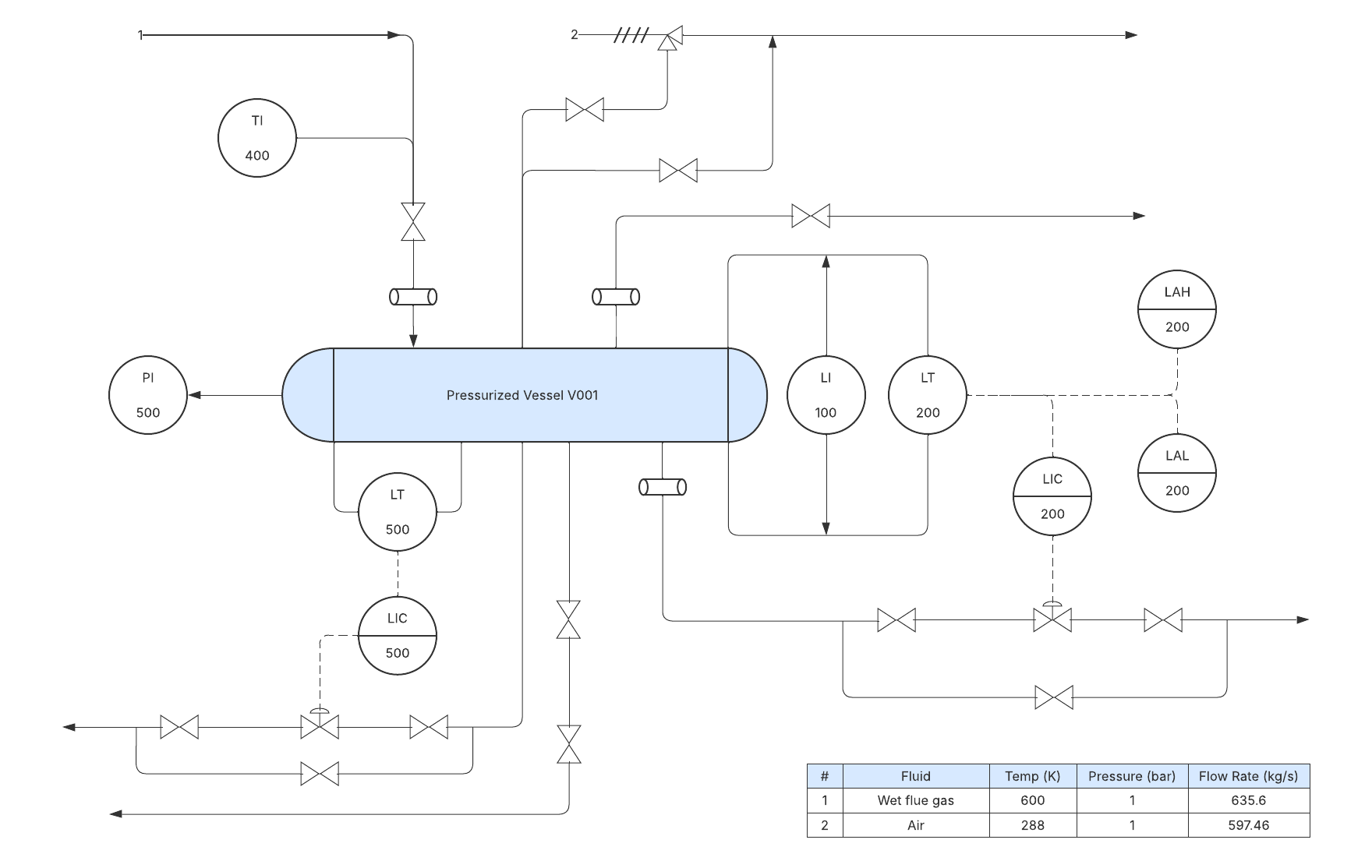
Enable and open the process engineering shape library, opens in a new tab so the symbols appear in your Shape menu.
Drag the equipment, piping, instrument, and valve shapes you need onto the canvas.
Connect the shapes with lines to show piping routes, then label each symbol and add instrument tags.
Import custom SVG shapes when you need symbols beyond the standard set. Then add and customize shapes, opens in a new tab to match your legend.
For a full walkthrough of building a diagram from these symbols, follow the step-by-step P&ID tutorial, opens in a new tab. To bring in shapes from other tools, see how to import files into Lucidchart, opens in a new tab.
Create your own P&ID with a free Lucidchart account
Sign up now