Key takeaways
UML defines 14 standardized diagram types—seven structural and seven behavioral—giving teams a common visual language for software design.
The Object Management Group (OMG) has maintained UML since adopting it as a standard in 1997, with UML 2.5.1 as the current formal specification.
Choosing the right diagram type starts with defining your goal: Structural diagrams (class, component, deployment, and others) capture what a system contains, while behavioral diagrams (sequence, activity, use case, and others) capture how it behaves.
Treating UML diagrams as living documentation keeps them useful in Agile environments, accelerating onboarding and cross-team communication.
Lucidchart's AI diagram creation, UML shape libraries, real-time collaboration, and text-to-diagram markup make it easy to create and maintain UML diagrams at any scale.
What is UML?
UML (Unified Modeling Language) is a standardized visual modeling language for designing, documenting, and communicating the architecture and behavior of software systems. Think of it as a blueprint for software. Just as architects use blueprints to plan buildings, developers and engineers use UML diagrams to plan and explain how systems work.
UML combines object-oriented design, object modeling technique, and object-oriented software engineering into a single, semantically rich notation. Because UML is standardized, UML diagrams are readable across programming languages, development methodologies, and organizations. This consistency reduces ramp-up time for new team members and makes cross-functional communication faster.
Beyond design, UML also serves as visual documentation. Teams that maintain UML diagrams spend less time re-explaining system architecture and more time building.
What is the history of UML?
UML emerged in the mid-1990s when Grady Booch, James Rumbaugh, and Ivar Jacobson unified their separate modeling approaches into a single language. They released UML 0.9 and 0.91 drafts in 1996, attracting support from Microsoft, Oracle, and IBM. They later published “The Unified Modeling Language User Guide” in 1999, with a second edition covering UML 2.0 in 2005.
The Object Management Group (OMG) adopted UML as a standard in 1997 (UML 1.1), establishing it as an industry-wide specification.
What role does the Object Management Group play in UML?
The Object Management Group, opens in a new tab (OMG) is an international, open-membership, not-for-profit technology standards consortium founded in 1989. OMG oversees the definition and maintenance of the UML specification, ensuring the language evolves to meet modern software development needs.
Key UML requirements maintained by OMG include:
A MOF-based meta-model
Defined semantics for each diagram element
Consistent notation rules
XMI interchange for tool compatibility
The current formal specification is UML 2.5.1, opens in a new tab, adopted in December 2017.
What are the types of UML diagrams?
UML currently defines 14 diagram types divided into two groups: structural and behavioral. Structural diagrams show the static elements of a system, including its components and their relationships. Behavioral diagrams show how those components interact over time.
Structural UML diagrams
Structural diagrams capture what a system contains:
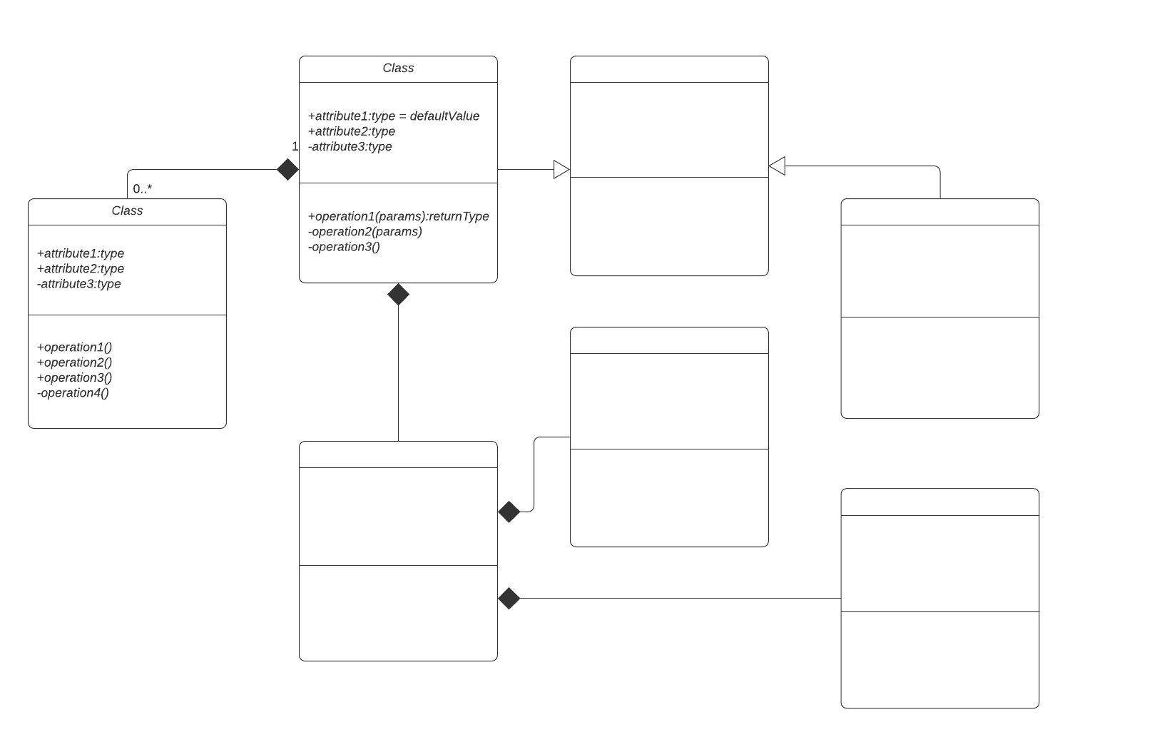
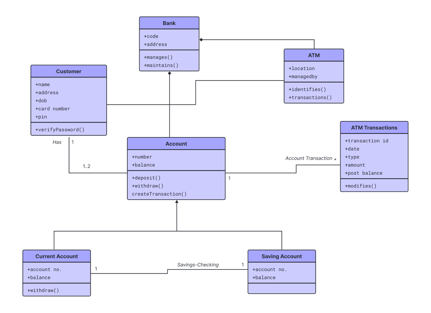
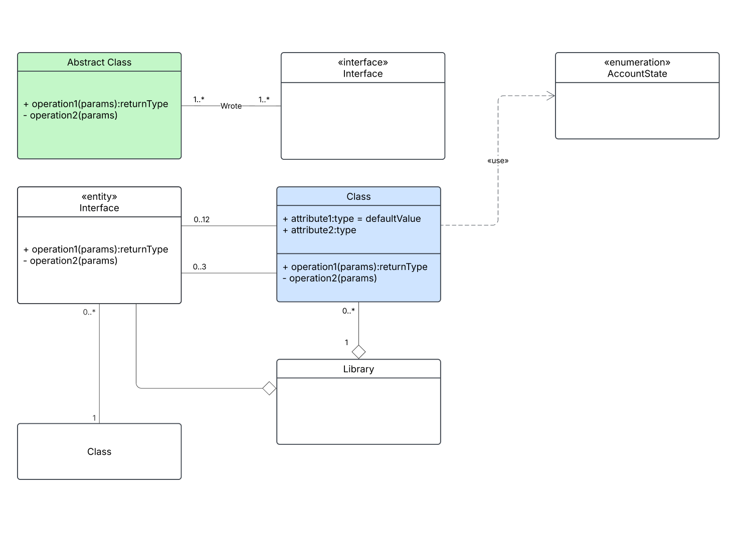
Class diagrams, opens in a new tab show classes, attributes, operations, and the relationships between them.
Component diagrams, opens in a new tab illustrate how software components are organized and depend on each other.
Composite structure diagrams, opens in a new tab detail the internal structure of a class or component.
Deployment diagrams, opens in a new tab map software artifacts to physical hardware nodes.
Object diagrams, opens in a new tab show a snapshot of object instances at a specific moment.
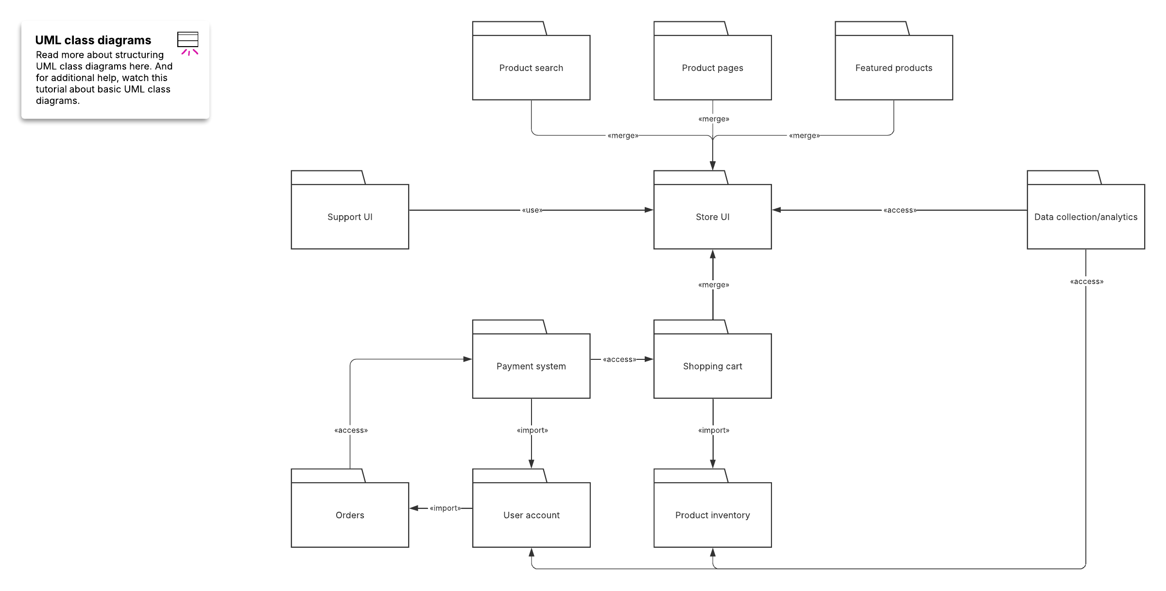
Package diagrams, opens in a new tab group related elements into packages for organization.
Profile diagrams, opens in a new tab are a UML extensibility mechanism that tailors the language with domain-specific stereotypes.
Behavioral UML diagrams
Behavioral diagrams capture how a system behaves:
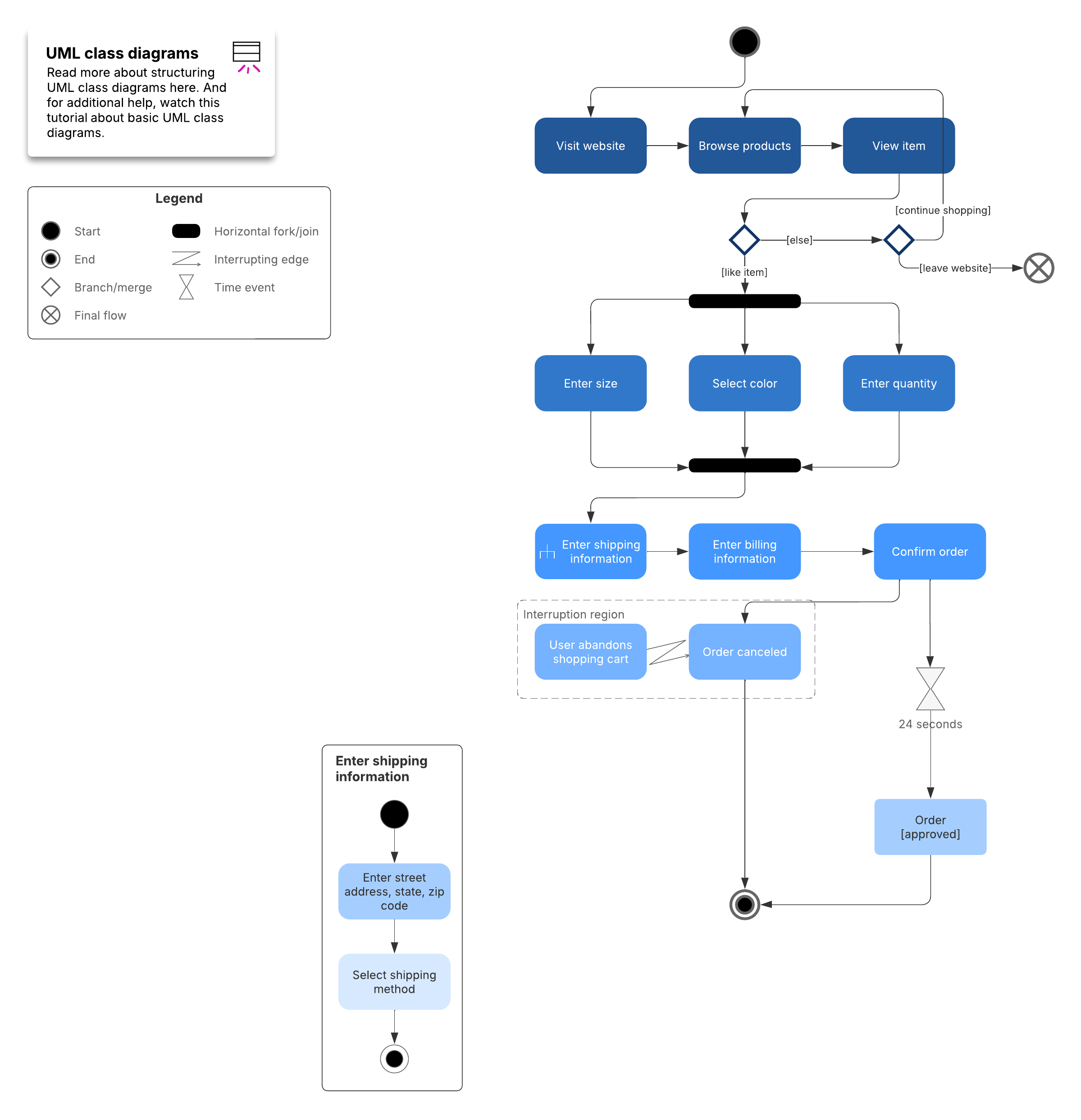
Activity diagrams, opens in a new tab model workflows and the flow of control between activities.
Communication diagrams, opens in a new tab show how objects interact through messages.
Interaction overview diagrams, opens in a new tab combine activity and sequence diagrams to show control flow.
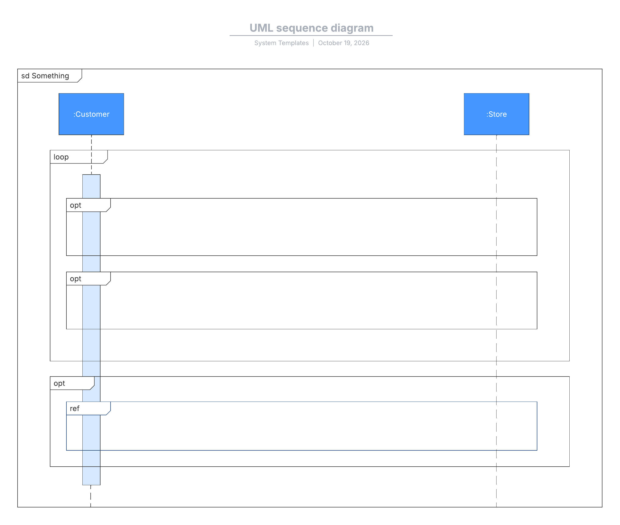
Sequence diagrams, opens in a new tab detail the order of messages exchanged between objects over time.
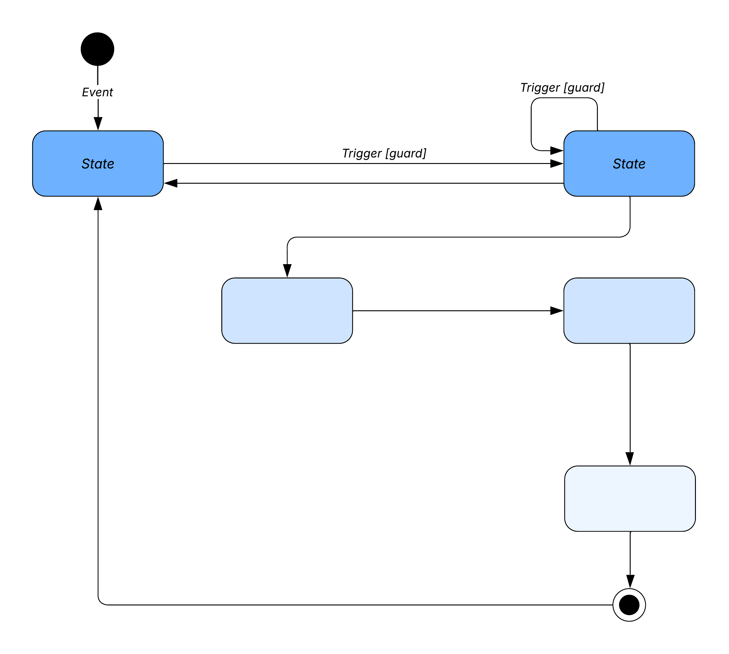
State machine diagrams, opens in a new tab illustrate how an object transitions between states.
Timing diagrams, opens in a new tab show state changes along a timeline.
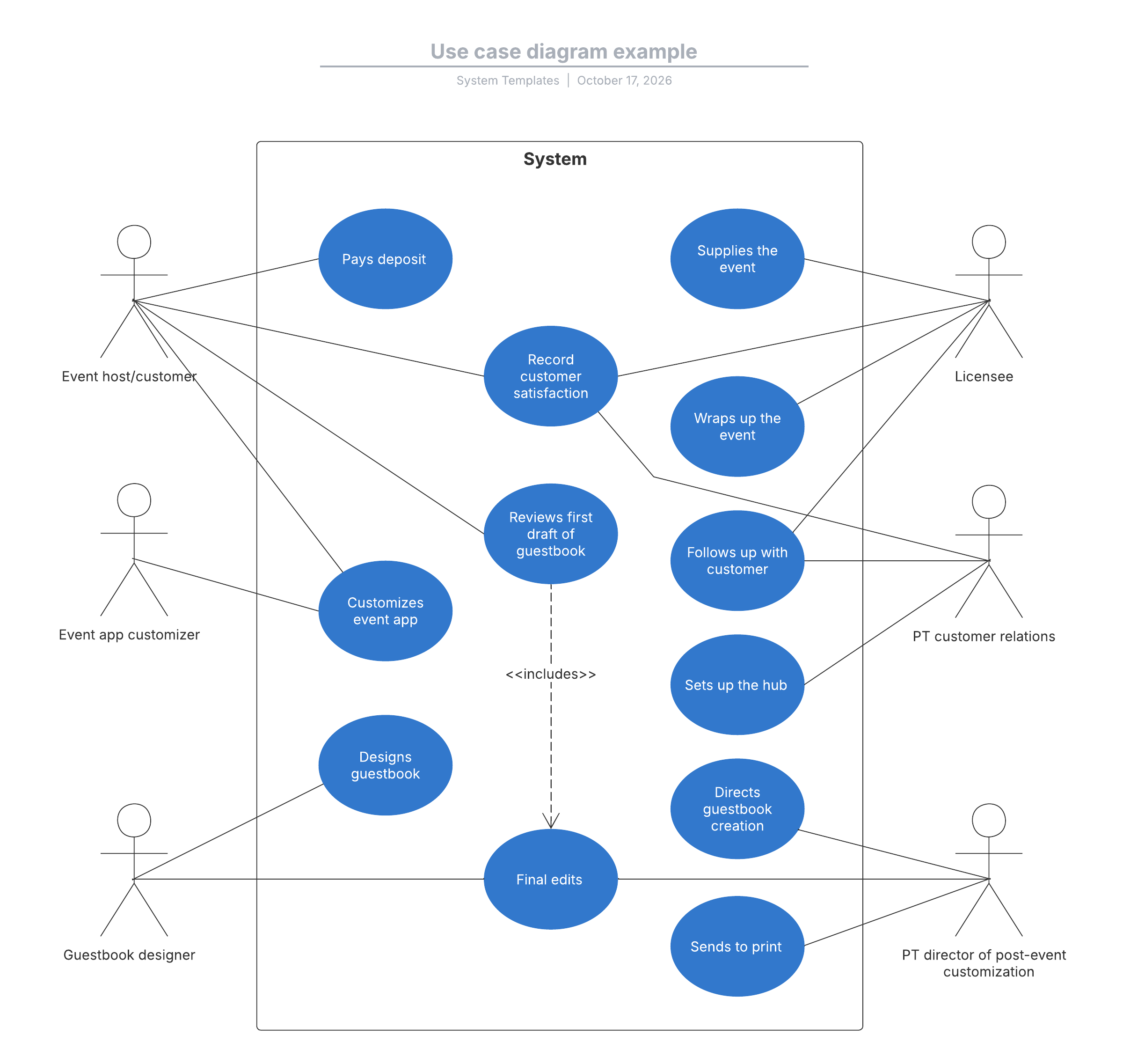
Use case diagrams, opens in a new tab capture user interactions and system goals.
What do common UML terms mean?
Understanding UML terminology helps you read and create diagrams more effectively. The following terms appear frequently in UML:
Term | Definition |
abstract syntax compliance | a tool adheres to the UML meta-model structure |
concrete syntax compliance | a tool renders UML notation correctly |
core | the foundational elements of the UML meta-model |
language unit | a grouping of related UML constructs (for example, classes or interactions) |
L0 | the minimal UML compliance level |
LM (metamodel constructs) | extended meta-model features beyond L0 |
MOF (Meta-Object Facility) | the framework that defines how UML is structured |
OCL (Object Constraint Language) | a language for specifying rules and constraints on UML elements |
XMI (XML Metadata Interchange) | the XML format for exchanging UML models between tools |
MDA (Model-Driven Architecture) | an approach that uses models, including UML, to drive development |
How does UML represent modeling concepts?
UML organizes system models into three perspectives.
Functional model: Captured through use case diagrams, the functional model shows what the system does from the user's point of view.
Object model: Captured through class diagrams, the object model shows the structure of the system, including classes, attributes, and relationships.
Dynamic model: Captured through interaction diagrams such as sequence and communication diagrams, state machine diagrams, and activity diagrams, the dynamic model shows how the system behaves over time.
These perspectives work together to give stakeholders a complete picture, from high-level user goals down to detailed runtime behavior.
What object-oriented concepts does UML use?
UML is rooted in object-oriented programming principles. Familiarity with these concepts makes UML diagrams easier to read and create:
Object: a specific instance of a class with its own state and identity
Class: a blueprint defining attributes and operations for objects
Abstraction: hiding complexity by exposing only relevant details
Encapsulation: bundling data and methods, controlling access through visibility
Inheritance: allowing one class to derive attributes and behavior from another
Polymorphism: enabling objects to be treated as instances of their parent class while behaving differently
Why do teams still use UML diagrams in Agile?
Agile teams often question whether creating UML diagrams is worth the time, especially when requirements change quickly. The key is treating UML diagrams as living documentation rather than static artifacts.
When maintained alongside code, UML diagrams:
Accelerate onboarding: New team members understand system architecture faster.
Simplify navigation: Diagrams provide a visual map of how source code is organized.
Improve planning: Teams can sketch new features and dependencies before writing code.
Bridge communication gaps: Diagrams help technical and non-technical stakeholders align.
Lucidchart supports this approach with features like Lucid AI and UML sequence markup, opens in a new tab, which lets you generate sequence diagrams from text. These features make updating diagrams as fast as editing a few lines of code.
How do you create a UML diagram?
Follow these steps to create a UML diagram manually in Lucidchart.
1. Define your goal
Decide what you want to communicate. If you need to show system structure (classes, components, deployment), choose a structural diagram. If you need to show behavior (workflows, interactions, state changes), choose a behavioral diagram.
2. Choose the right diagram type
Match your goal to one of the 14 UML diagram types. Starting with a premade UML template, opens in a new tab can save time and ensure you follow standard conventions.
3. Enable UML shape libraries
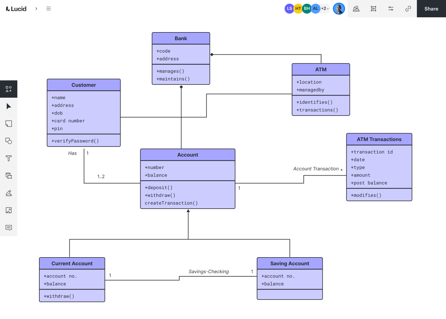
In Lucidchart, open the left panel, click the Search icon, then select Shapes > Browse all shapes. Search for "UML" and check the boxes for the shape libraries you need (for example, UML Class, UML Sequence, or UML Use Case).
4. Add and define your shapes
Drag shapes onto the canvas. Double-click a shape to add text, attributes, or operations. Use naming conventions that match your codebase or design standards.
5. Connect your components
Draw lines between shapes to represent relationships. Customize endpoints to communicate the nature of each relationship. Use arrowheads for inheritance, diamonds for composition, and dashed lines for dependencies.
6. Review and collaborate
Share your diagram with teammates using Lucidchart's real-time collaboration. Gather feedback, refine details, and keep the diagram updated as the system evolves. If you are still comparing options, explore the best UML diagram software, opens in a new tab to find tools that fit your workflow.
Create a UML diagram with Lucid AI
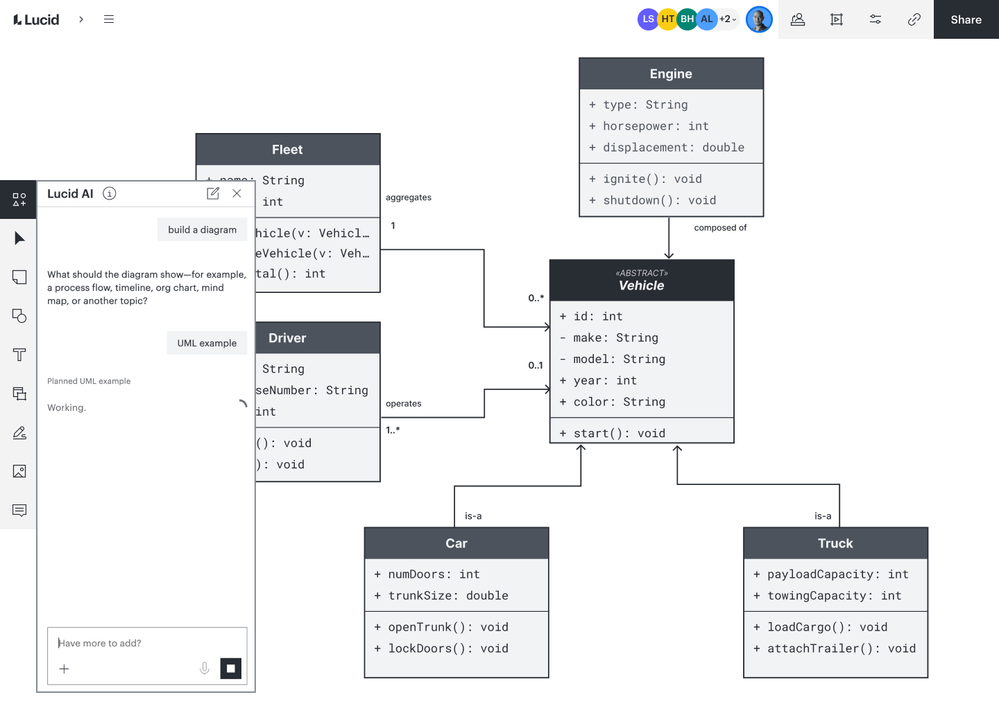
Rather than building a UML diagram manually or with a template, you can also use Lucid AI, opens in a new tab to create a diagram in seconds from a text prompt. To access the Lucid AI diagram maker, click the Lucid AI button on the left side of the editor. From there, type a description of the UML diagram you’d like to create. In seconds, Lucid AI will make a diagram for you that you can iterate on until it’s ready, saving you time and effort.
UML diagrams tutorial: How to build your own with Lucidchart video
Watch this walkthrough from the Lucid Software team for a quick tour of UML. The video covers:
The history and purpose of UML
The difference between structural and behavioral diagrams
How to choose the right diagram type
Professional UML notations and standards
Best practices for keeping diagrams readable
How to build UML diagrams in Lucidchart.
Become a UML evangelist
Sometimes it is not enough to be on board with UML yourself. As a developer, you usually work with teams, so it helps to bring everyone along. If your team is reluctant, propose using UML diagrams on just one project to start. Once they see how much clearer documentation and planning become, adopting UML as a standard step becomes an easy sell.
Create your own UML diagram when you sign up for Lucidchart.
Try it free